System and method for variable beacon timing with wireless devices

Active Publication Date: 2010-05-06
MEDTRONIC MIMIMED INC
View PDF99 Cites 98 Cited by
  • Summary
  • Abstract
  • Description
  • Claims
  • Application Information

AI Technical Summary

Benefits of technology

[0007]The above and other aspects may be carried out by an embodiment of a variable beacon timing method for a first wireless device and a second wireless device. The method begins by periodically transmitting beacons from the first wireless device to the second wireless device at a first rate during a first operating mode. Then, the first wireless device initiates a switch from the first operating mode to a second operating mode, and transmits a control beacon to the second wireless device. The control beacon is transmitted in accordance with the first rate, and the control beacon conveys a mode switching command for the second wireless device. Thereafter, the first wireless device periodically transmits beacons at a second rate during the second operating mode.
[0008]Another embodiment of a variable beacon timing method for a first wireless device and a second wireless device is also provided. This method begins by transmitting beacons from the first wireless device to the second wireless device during a first operating mode and in accordance with a first time schedule. The first wireless device receives a control message from the second wireless device, the control message conveying a mode switching request. Thereafter, the first wireless device periodically transmits beacons during the second operating mode and in accordance with a second time schedule and the second wireless device also switches to the second operating mode and in accordance with the second time schedule.
[0009]Yet another variable beacon timing method for a first wireless device and a second wireless device is provided. This method involves: periodically monitoring for beacons transmitted by the first wireless device at a first rate during a first operating mode, the beacons including a control beacon that conveys a mode switching command for the second wireless device, and receiving the control beacon and the mode switching command. In response to the mode switching command, the second wireless device switches from the first operating mode to the second operating mode. There

Problems solved by technology

Unfortunately, this type of configuration results in excessive power consumption because the beacon transmitting devices must support the fixed beacon interval even during periods when no data needs to be communicated.
In turn,

Method used


Image

  • System and method for variable beacon timing with wireless devices
  • System and method for variable beacon timing with wireless devices
  • System and method for variable beacon timing with wireless devices

Examples


first embodiment

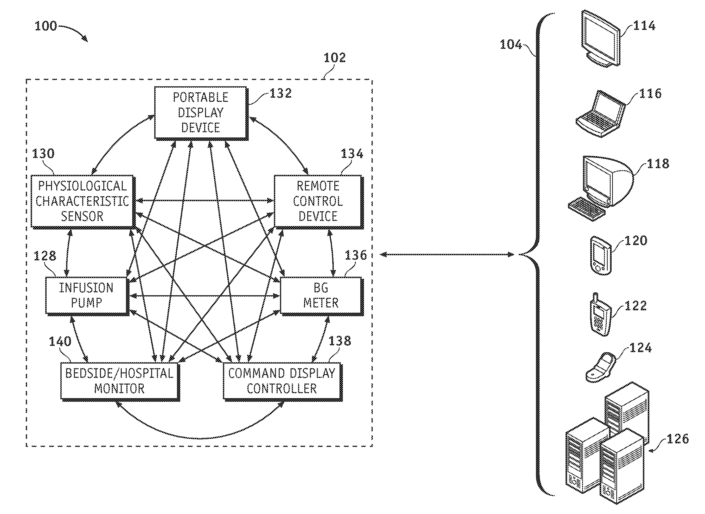
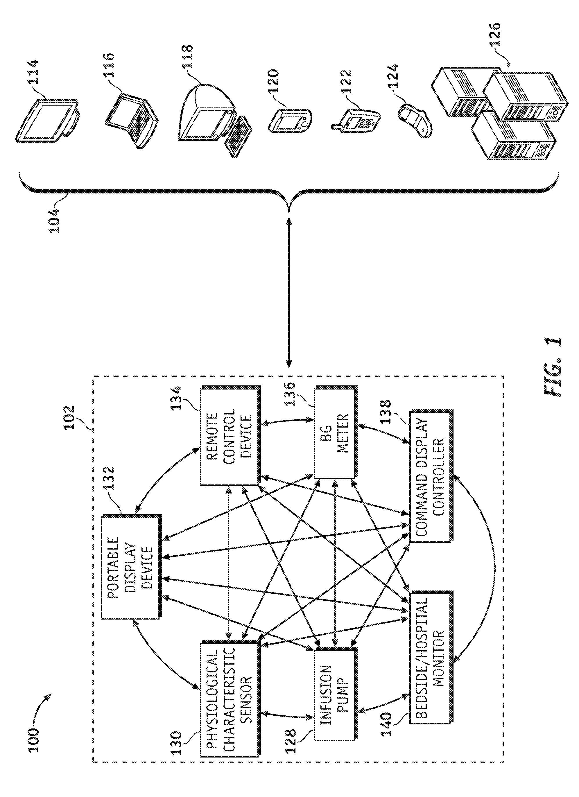
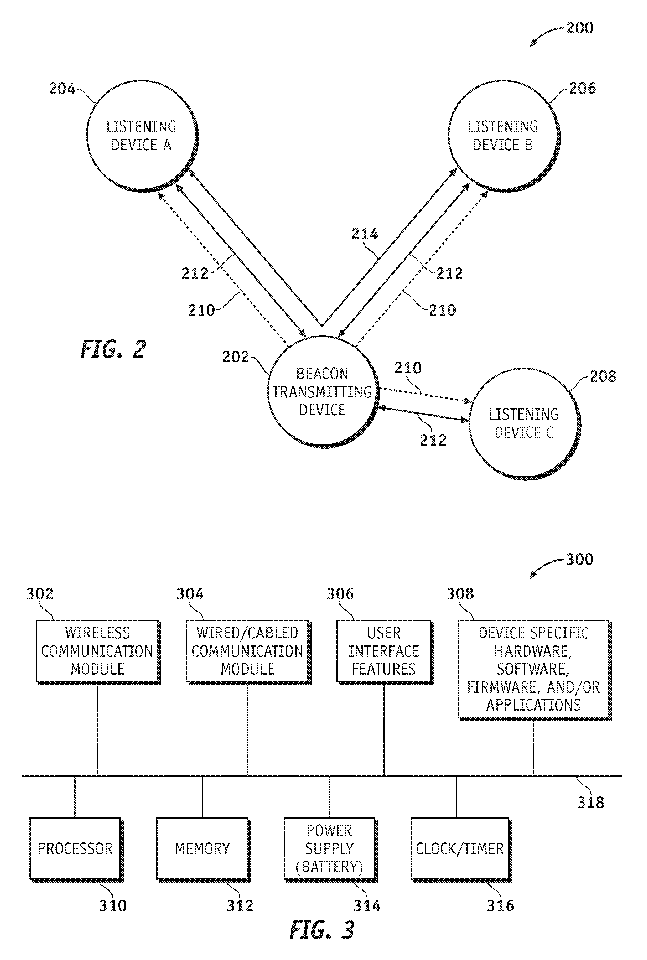
[0056]FIG. 4 is a flow chart that illustrates a first embodiment of a variable beacon timing process 400. For this embodiment of process 400, the beacon-transmitting wireless device initiates the transition from the power saving mode to the active communication mode. In addition, the wireless devices remain in the active communication mode for a fixed period of time before transitioning back to the power saving mode. The various tasks performed in connection with process 400 may be performed by software, hardware, firmware, or any combination thereof. For illustrative purposes, the following description of process 400 may refer to elements mentioned above in connection with FIGS. 1-3. In practice, portions of process 400 may be performed by different elements of the described system, e.g., the beacon-transmitting wireless device, the listening wireless device, or components thereof. It should be appreciated that process 400 may include any number of additional or alternative tasks, ...

second embodiment

[0068]FIG. 5 is a flow chart that illustrates a second embodiment of a variable beacon timing process 500. For this embodiment of process 500, the listening wireless device (i.e., the beacon-receiving wireless device) initiates the transition from the power saving mode to the active communication mode. In addition, the wireless devices remain in the active communication mode until certain conditions are met. The various tasks performed in connection with process 500 may be performed by software, hardware, firmware, or any combination thereof. For illustrative purposes, the following description of process 500 may refer to elements mentioned above in connection with FIGS. 1-3. In practice, portions of process 500 may be performed by different elements of the described system, e.g., the beacon-transmitting wireless device, the listening wireless device, or components thereof. It should be appreciated that process 500 may include any number of additional or alternative tasks, the tasks...

third embodiment

[0077]FIG. 6 is a flow chart that illustrates a third embodiment of a variable beacon timing process 600. For this embodiment of process 600, the listening wireless device (i.e., the beacon-receiving wireless device) initiates the transition from the power saving mode to the active communication mode. In addition, the wireless devices remain in the active communication mode for a designated period of time, which can be refreshed or reset as needed. The various tasks performed in connection with process 600 may be performed by software, hardware, firmware, or any combination thereof. For illustrative purposes, the following description of process 600 may refer to elements mentioned above in connection with FIGS. 1-3. In practice, portions of process 600 may be performed by different elements of the described system, e.g., the beacon-transmitting wireless device, the listening wireless device, or components thereof. It should be appreciated that process600 may include any number of ad...


PUM


Abstract

Systems and methods for supporting variable beacon timing for a first wireless device and a second wireless device are provided. An exemplary system may include a number of wireless devices configured to wirelessly communicate with one another. The system includes a beacon-transmitting wireless device and a listening wireless device. The beacon-transmitting wireless device is configured to transmit, during a first operating mode, wireless beacons separated in time by relatively long time intervals. The beacon-transmitting device is also configured to transmit, during a second operating mode, wireless beacons separated in time by relatively short time intervals. The listening wireless device is configured to listen, during the first operating mode, for wireless beacons transmitted by the beacon-transmitting wireless device, and is configured to listen, during the second operating mode, for wireless beacons transmitted by the beacon-transmitting wireless device. The system may have more than two different operating modes, which may be desirable if the number of wireless devices in the system exceeds two.

Description

TECHNICAL FIELD[0001]Embodiments of the subject matter described herein relate generally to wireless communication and wireless systems. More particularly, the embodiments relate to systems and techniques related to the transmission of beacons in a wireless system, such as a medical device network environment that includes wireless devices.BACKGROUND[0002]Wireless devices and related wireless communication techniques and protocols have become ubiquitous in modern society. Indeed, the prior art is replete with wireless devices such as cellular telephones, mobile computers, personal digital assistants, digital media players, portable video game devices, and the like. Moreover, portable medical devices having wireless data communication capabilities are becoming increasingly popular, especially for patients that have conditions that must be monitored on a continuous or frequent basis. For example, diabetics are usually required to modify and monitor their daily lifestyle to keep their ...

Claims


Application Information

Patent Timeline
IPC IPC(8): H04J3/00
CPCH04W52/0216Y02D70/1224Y02D70/142Y02D70/162Y02D70/146Y02D70/22Y02D70/144Y02D30/70
Inventor MEHTA, KAEZAD J.
Owner MEDTRONIC MIMIMED INC
Why Eureka
Try Eureka