Controlling session keys through in-band signaling

Active Publication Date: 2010-05-06
CIENA
View PDF18 Cites 37 Cited by
  • Summary
  • Abstract
  • Description
  • Claims
  • Application Information

AI Technical Summary

Benefits of technology

[0008]The frames include a payload for carrying the encrypted traffic and associated overhead that is used to carry control information. The control information is used to assist in controlling the delivery and processing the traffic. The session keys used by the PTEs to encrypt and decrypt the traffic are provisioned and controlled through key messaging that is exchanged between the PTEs. The key messaging is exchanged between the PTEs in the overhead of the frames. As such, the key messaging may be provided in the overhead of the frames along with other control information. A single message may be broken into numerous message portions and transported from one PTE to another over numerous frames to reduce the impact of the key messaging on the available overhead. Exchanging key messaging between PTEs in the overhead of frames is referred to as in-band key messaging. Key messaging includes messaging provided between PTEs and related to generating, selecting, changing, or otherwise controlling the session keys that are used by the PTEs to encrypt and decrypt traffic.
[0009]As indicated, the session keys are used for encrypting and decrypting traffic carried in the frames, and key messages are used to control the session keys. To enhance security, the key messages may be encrypted using master keys, which may be symmetric or asymmetric keys and are preferably different from the session keys. As such, a first PTE may generate a key message, encrypt the key message or portions of the key message, and map the key message or

Problems solved by technology

The changing of the key poses logistical and operational issues, as special mechanisms must be provided to ensure that unauthorized entities do not gain access to the key.
Such access could allow third parties to improper

Method used


Image

  • Controlling session keys through in-band signaling
  • Controlling session keys through in-band signaling
  • Controlling session keys through in-band signaling

Examples


Example

[0022]The embodiments set forth below represent the necessary information to enable those skilled in the art to practice the invention and illustrate the best mode of practicing the invention. Upon reading the following description in light of the accompanying drawing figures, those skilled in the art will understand the concepts of the invention and will recognize applications of these concepts not particularly addressed herein. It should be understood that these concepts and applications fall within the scope of the disclosure and the accompanying claims.

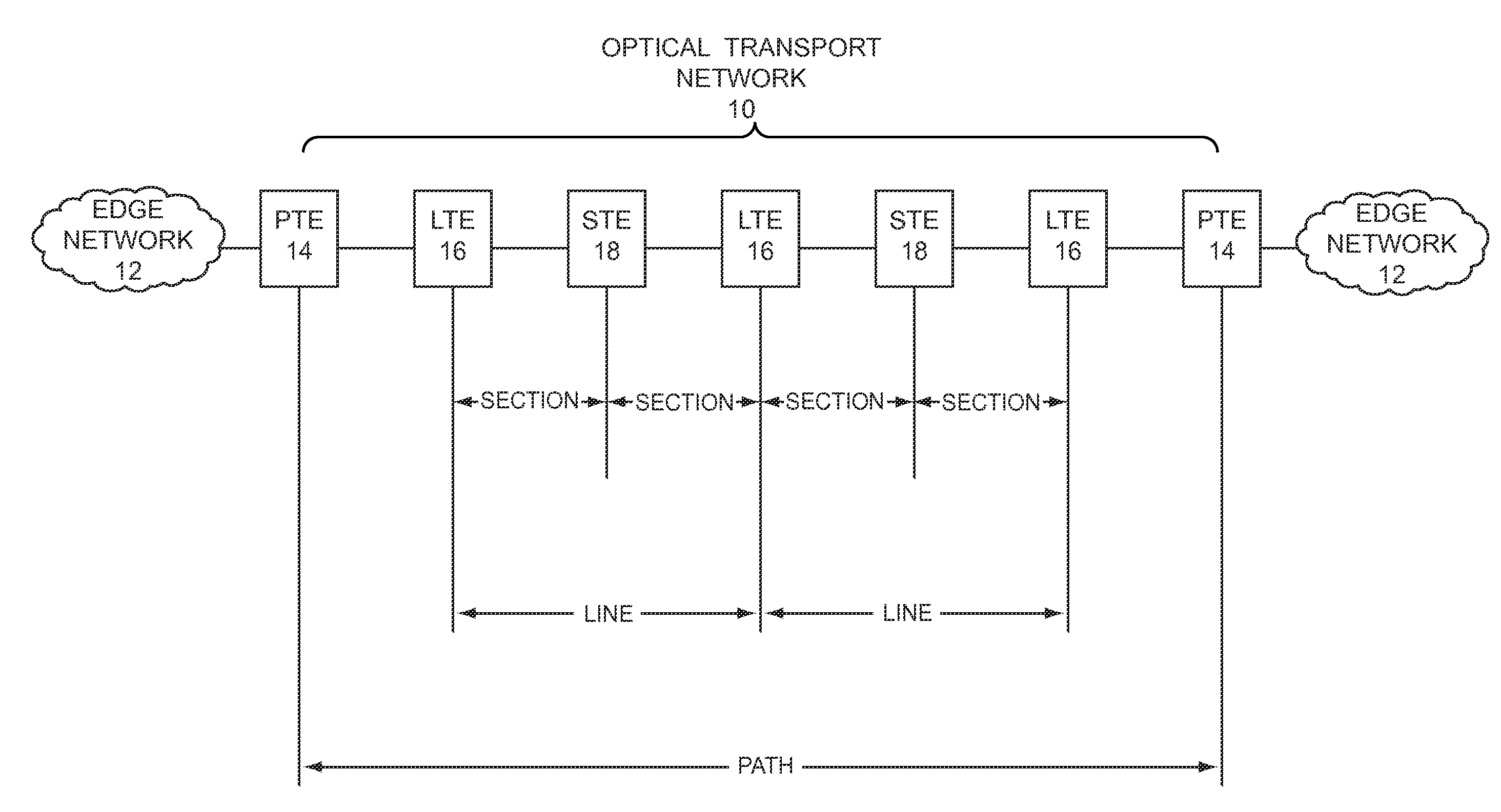
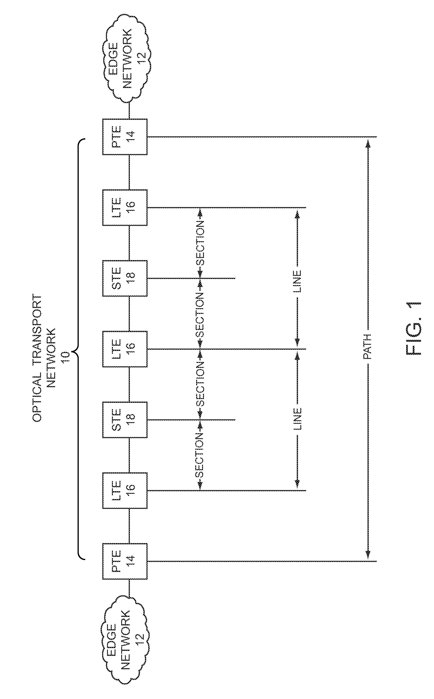
[0023]The present invention employs in-band signaling between transport nodes to provision and control session keys, which are used by the transport nodes for encrypting and decrypting traffic that is carried from one transport node to another over a transport network. Transport nodes are generally referred to as path termination equipment (PTE), and terminate paths that extend across all or a portion of a transport network. Encry...


PUM


Abstract

The present invention employs in-band signaling between PTEs to provision and control session keys, which are used by the PTEs for encrypting and decrypting traffic that is carried from one PTE to another over a transport network. In operation, a first PTE will receive incoming traffic from a first edge network, map the traffic to frames, encrypt the traffic with a session key, and send the frames with the encrypted traffic over the transport network to a second PTE. The second PTE will extract the encrypted traffic from the frames, decrypt the encrypted traffic with a session key, and send the recovered traffic over a second edge network toward an intended destination. If symmetric encryption is employed, the session key used by the first PTE to encrypt the traffic will be identical to the session key used by the second PTE to decrypt the traffic.

Description

FIELD OF THE INVENTION[0001]The present invention relates to communications, and in particular to controlling session keys through in-band signaling.BACKGROUND OF THE INVENTION[0002]Transport networks are under continual demand to carry more information at higher speeds and lower costs, and optical networks are playing a critical role in addressing this demand. Optical transport networks provide an optical-based physical layer for transmitting information across the network. One of the main characteristics of optical transport networks is the use of frame structured digital bit streams to transport data across the network. The frames typically have a payload area and an overhead area, which contains control information. The frame overhead is analogous to the header of an Internet Protocol packet. The path through an optical transport network generally extends between two edge devices, which are generally referred to as path termination equipment (PTE). Along the path through the opt...

Claims


Application Information

Patent Timeline
IPC IPC(8): H04L9/06
CPCH04L9/0841H04L9/3271Y02D30/32H04L63/0823H04L63/061Y02D30/00
Inventor HU, XIAOQINGSIMARD, FREDERIC F.
Owner CIENA
Why Eureka
Try Eureka