
Registration and visualization of image structures based on confiners

Inactive Publication Date: 2010-05-06
MATTES DR JULIAN
View PDF2 Cites 4 Cited by
  • Summary
  • Abstract
  • Description
  • Claims
  • Application Information

AI Technical Summary

Benefits of technology

[0010]It is an object of the invention to avoid the problems associated with the identification of corresponding blobs, in particular associated to previous approaches looking for corresponding confiner pairs, which are sensitive to differences in both images due to noise or different conditions of image acquisition.
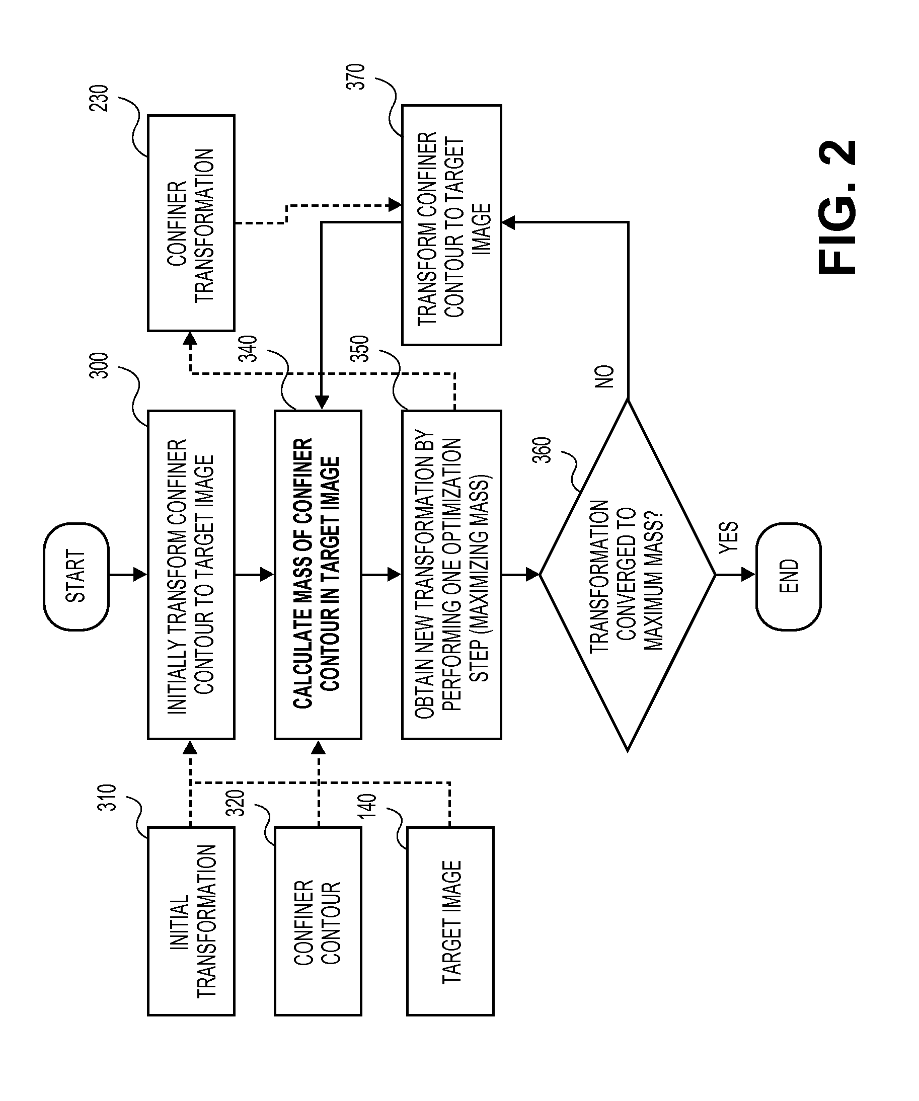
[0012]To avoid the problems associated with the identification of corresponding blobs the invention proposes to set the registration task as a hierarchical contour-to-image template matching problem and by defining a new similarity metric for contour- (or region-) to-image matching. The proposed similarity measure is based on a maximal mass confinement principle. This measure and strategy lead to a simple but efficient method not only for contour-to-image matching but also for rigid and locally rigid image registration usually able to cope with large local movements.
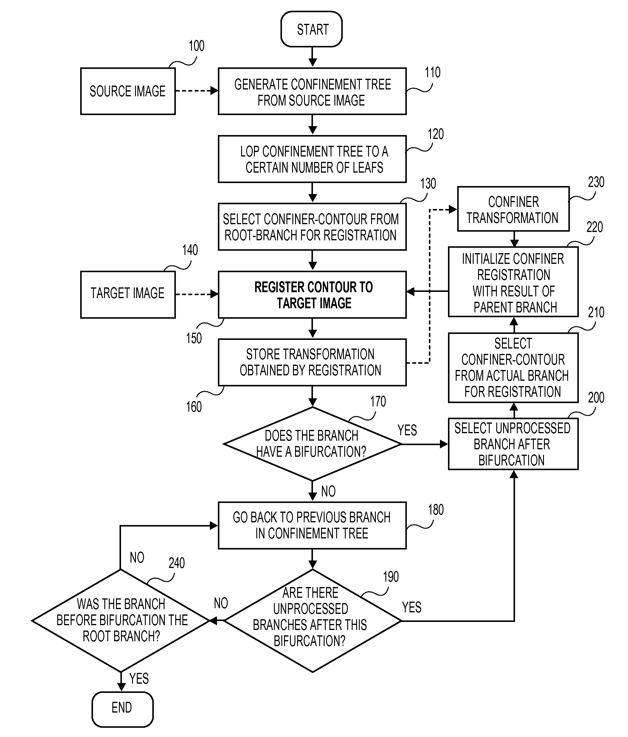
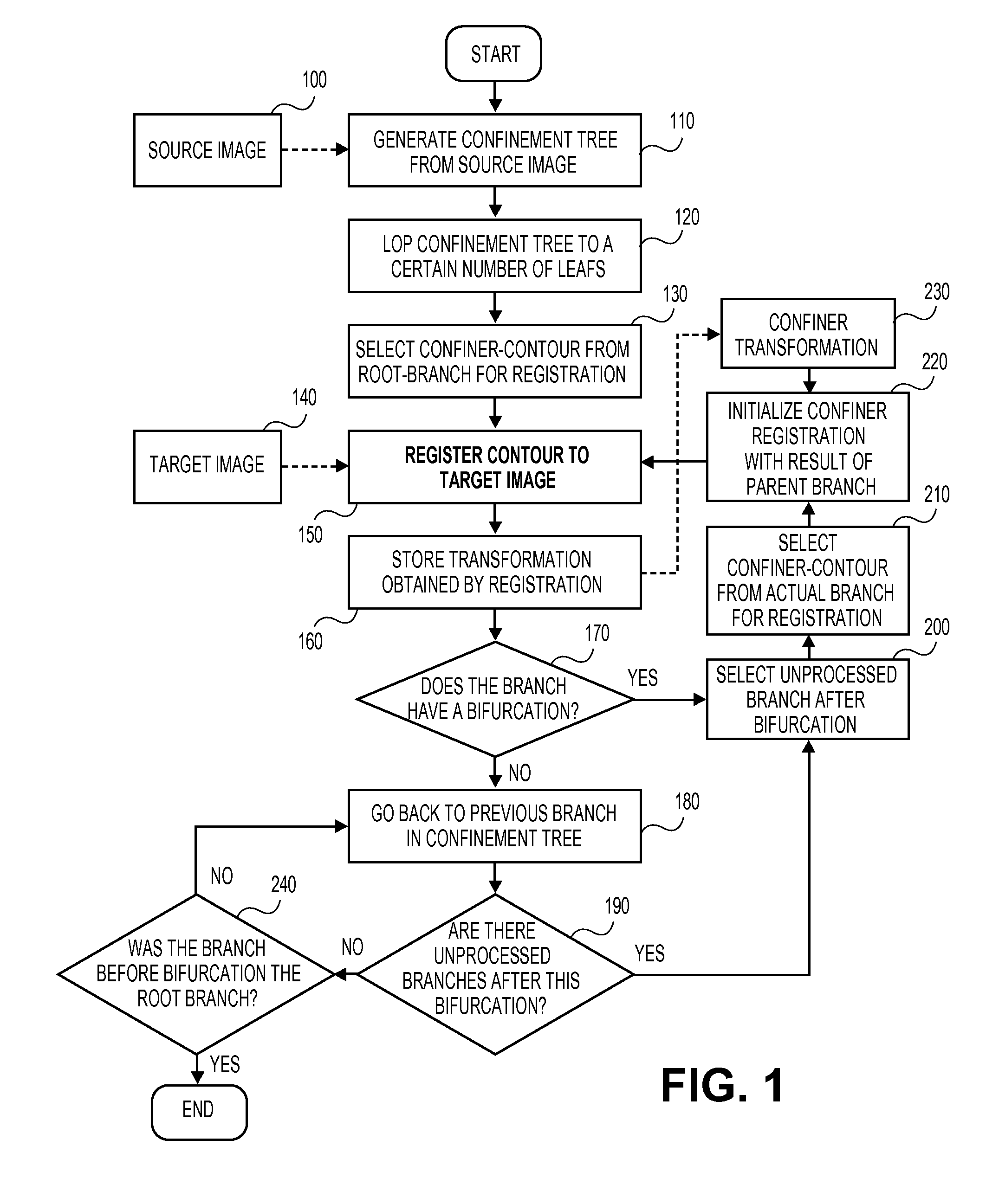
[0014]Basically, the invention provides to set the problem of image registration as a contour / region-template-to-image matching problem using so-called confiners—also called blobs or components—as template regions, to select the confiners of one of the images by passing through the hierarchical structure which they define and registering them successively rigidly form coarse-to-fine to the other image, the target image, and to use a maximum mass confinement (MMC) principle for contour-to-image registration. This principle allows to derive a similarity measure assessing how well the confiner fits into the target image simply by calculating the gray value mass confined by its contour. By optimizing this measure for rigid transformations a MMC algorithm registering a contour locally rigid to the target image is obtained. According to this principle of the invention, problems can be avoided which were related to previous registration algorithms based on confiners.

Problems solved by technology

However, small differences in both images (e.g., because of noise) often lead to considerable changes of the blobs of the respective images, even though parts of them may still correspond.

Method used


Image

  • Registration and visualization of image structures based on confiners
  • Registration and visualization of image structures based on confiners
  • Registration and visualization of image structures based on confiners

Examples


Embodiment Construction

[0040]The described exemplary embodiments are intended to assist in the understanding of the invention and are not intended to limit the scope of the invention in any way.

[0041]FIG. 1 is a flow chart describing the principle steps of a method for registering image structures according to an embodiment of the invention. The confinement tree is generated as it will be described in more detail below in step 110 from a source image 100. The confinement tree is loped to a certain number of leaves in step 120. From the route branch of the confinement tree a confiner contour is selected for registration in step 130. The contour is then registered to a target image 140 in step 150. According to an embodiment, the region of the registered contour has an area corresponding to a respective region in the source image. If for example both the source image and the target image have the same dimension, the region of the registered contour has the same or nearly the same area as the respective regi...


PUM


Abstract

A method for registration of image structures is provided which comprises the steps of providing a source image and a target image each comprising a plurality of pixels, wherein each pixels has a gray value, defining at least one gray value level, determining one or more first regions in the source image for each gray value level as confiners, wherein the first region comprises pixels having gray intensities equal to or higher than the gray value level, selecting one of the one or more determined first regions, determining second regions in the target image which are equal to the selected first regions, calculating the mass of each determined second region by forming the sum of the gray intensities of all pixels of the determined second region, and determining the maximum of the calculated masses and selecting the second region having the maximum mass as corresponding to the first region in the target image.

Description

RELATED APPLICATION[0001]This application claims priority from EP patent application No. 08015612.8 filed on Sep. 4, 2008 and entitled “Registration and Visualization of Image Structures Based on Confiners” which is incorporated herein by reference.FIELD OF THE INVENTION[0002]The present invention is generally related to image-to-image and / or template-to-image registration, particularly to registration and visualization of image structures based on confiners and more particularly to a method and apparatus for registration of image structures.BACKGROUND OF THE INVENTION[0003]Image registration is defined as the process of determining the spatial transformation relating physically or anatomically corresponding points in two images or to bring them together as close as possible for a given class of transformations. Registration of a contour to a 2D image or of a surface to a 3D image is defined in the same way but only the points on the contour or surface have to be related, or brought...

Claims


Application Information

Patent Timeline
IPC IPC(8): G06K9/46
CPCG06T7/33
Inventor MATTES, JULIANGALL, JOHANNES
Owner MATTES DR JULIAN
Learn More