Glaucoma drainage shunts and methods of use

a shunt and glaucoma technology, applied in the field of eye glaucoma treatment, can solve problems such as flow restrictors, and achieve the effects of reducing heightened intraocular pressure, reducing hoop strength, and reducing hoop strength

Active Publication Date: 2010-05-06
JOHNSON & JOHNSON SURGICAL VISION INC
View PDF60 Cites 84 Cited by
  • Summary
  • Abstract
  • Description
  • Claims
  • Application Information

AI Technical Summary

Benefits of technology

[0013]According to one aspect of the inventions disclosed herein, a glaucoma drainage device is described along with methods of implantation that allow for controlled outflow of aqueous fluid to assist in reducing heightened intraocular pressure associated with glaucoma. In various embodiments, the drainage device includes a plate and a drainage tube having an open cross-section and connected to the plate such that an outflow end of the drainage tube connects to a part of the plate and an inflow end of the drainage tube extends away from the plate. The inflow end of the drainage tube is configured to be inserted through an incision at or near the limbus of an eye and into the anterior chamber of the eye, with the hoop strength of the drainage tube chosen such that the tube wall assumes a collapsed shape within the incision after insertion due to the pressure of the incision walls and/or a relatively sharp angle of insertion of the tube. The resiliency of the drainage tube is such that the tube wall will resiliently expand from its collapsed shape to its open cross-section within the in

Problems solved by technology

This results in a flow restrictor wherein the drainage tube gr

Method used


Image

  • Glaucoma drainage shunts and methods of use
  • Glaucoma drainage shunts and methods of use
  • Glaucoma drainage shunts and methods of use

Examples


Embodiment Construction

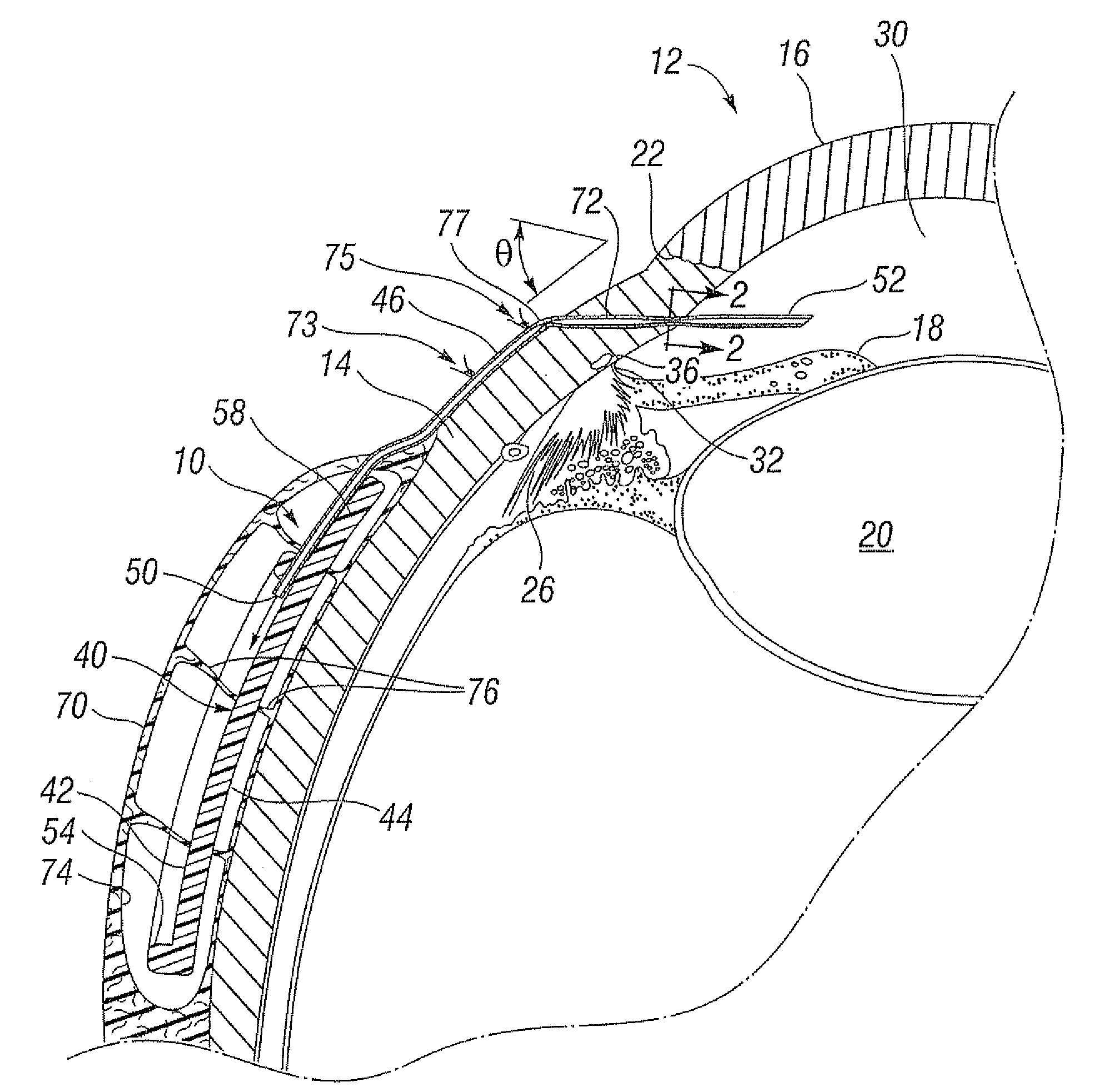
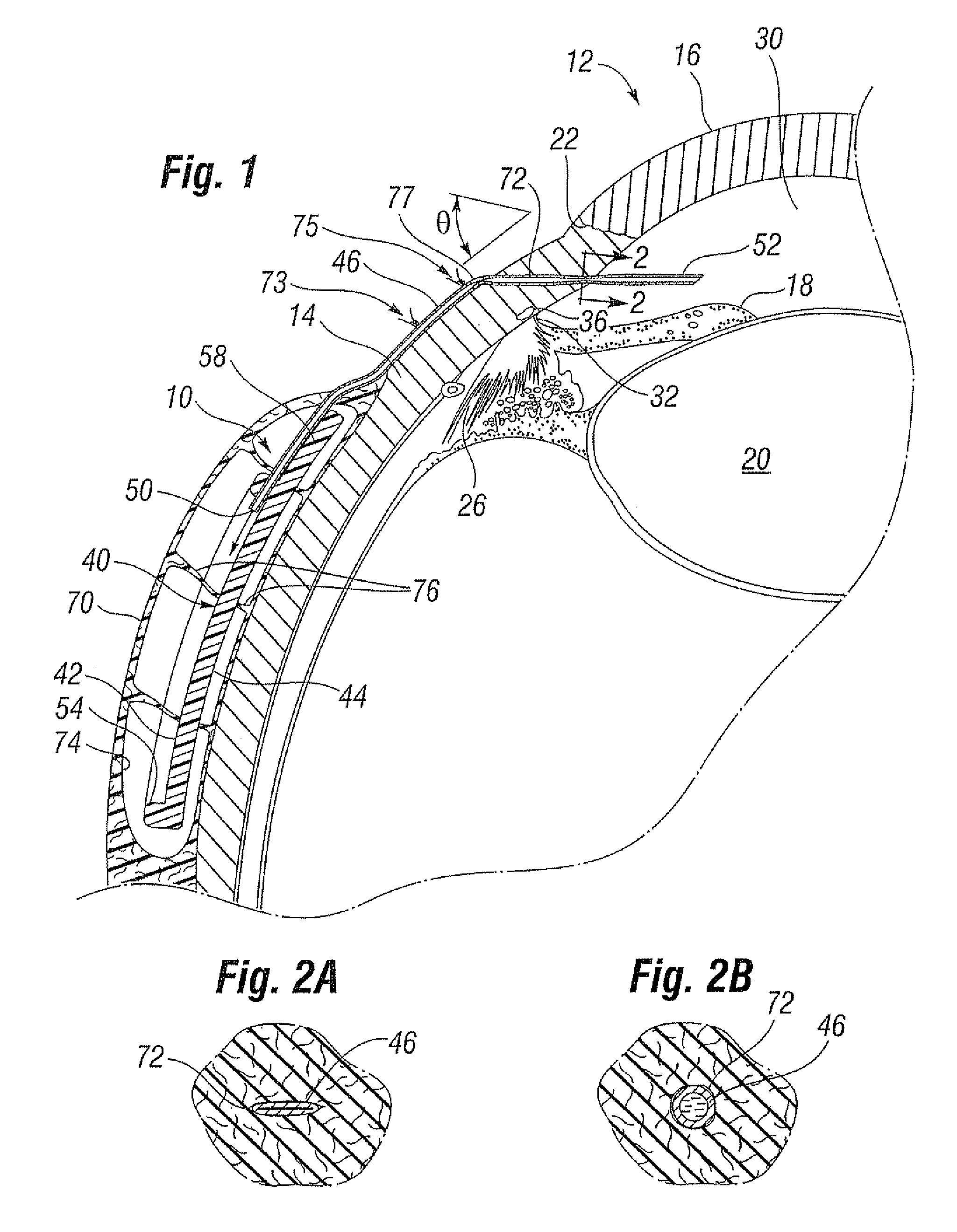
[0025]FIG. 1 illustrates a glaucoma shunt 10 constructed in accordance with the present invention positioned within the tissue of an eye 12. The relevant structure of the eye 12 will be described briefly below to provide background for the anatomical terms incorporated herein, however, it should be realized that several anatomical details have been omitted for clarity of understanding. The tough outer membrane known as the selera 14 covers all of the eye 12 except that portion covered by the cornea 16, the thin, transparent membrane which enables light to enter the pupil 18 and the iris aperture in front of the lens 20. The cornea 16 merges into the sclera 14 at a juncture referred to as the sulcus of the sclera or as the limbus 22. The ciliary body 26 begins at the limbus 22 and extends along the interior of the sclera 14.

[0026]It is well-known that aqueous is produced by the ciliary body 26 and reaches the anterior chamber 30 formed between the iris 18 and the cornea 16 through th...


PUM


Abstract

A method of treating glaucoma in an eye utilizing an implanted shunt having an elastomeric plate and a non-valved elastomeric drainage tube. The plate is positioned over a sclera of the eye with an outflow end of the elastomeric drainage tube open to an outer surface of the plate. An inflow end of the drainage tube tunnels through the sclera and cornea to the anterior chamber of the eye. The drainage tube collapses upon initial insertion within an incision in the selera and cornea, or at a kink on the outside of the incision, but has sufficient resiliency to restore its patency over time. The effect is a flow restrictor that regulates outflow from the eye until a scar tissue bleb forms around the plate of the slunt. The plate desirably has a peripheral ridge and a large number of fenestrations, and a longer suturing tab extending from one side of the plate to enhance visibility and accessibility when suturing the shunt to the selera.

Description

FIELD OF THE INVENTION [0001]The present invention relates to treatments for glaucoma in the eye and, more particularly, to glaucoma shunts and methods of use for draining fluid from the eye at a controlled rate.BACKGROUND OF THE INVENTION [0002]Intraocular pressure in the eye is maintained by the formation and drainage of aqueous, a clear, colorless fluid that fills the anterior and posterior chambers of the eye. Aqueous normally flows from the anterior chamber of the eye out through an aqueous outflow channel at a rate of 2 to 3 microliters per minute.[0003]Glaucoma is a progressive disease of the eye characterized by a gradual increase of intraocular pressure. This increase in pressure is most commonly caused by stenosis or blockage of the aqueous outflow channel, resulting in excessive buildup of aqueous fluid in the eyeball. Other causes include increase in venous pressure outside the eye which is reflected back through the aqueous drainage channels and increased production of ...

Claims


Application Information

Patent Timeline
IPC IPC(8): A61M39/00
CPCA61F9/00781A61F2009/00891Y10S623/905A61M27/002A61M2210/0612A61F9/007
Inventor BAERVELDT, GEORGE
Owner JOHNSON & JOHNSON SURGICAL VISION INC
Why Eureka
Try Eureka