Magnetic positioning of surgical mesh

a surgical mesh and magnetic positioning technology, applied in the field of magnetic positioning of surgical meshes, can solve the problems of mesh being relatively large, difficult to maneuver into a suitable position, and difficult to manipulate surgical mesh materials, etc., to achieve the effect of reducing the effort and difficulty of placing surgical meshes, facilitating maneuvering into a suitable position, and facilitating withdrawal

Inactive Publication Date: 2010-05-06
NEFF MARC
View PDF5 Cites 39 Cited by
  • Summary
  • Abstract
  • Description
  • Claims
  • Application Information

AI Technical Summary

Benefits of technology

[0003]The present invention reduces the effort and difficulty of placing a surgical mesh. The mesh may be pinned magnetically in place against the abdominal wall by sandwiching the mesh and tissue between two magnetically responsive members. One of these members must be a magnet and the other may be either magnetic or merely magnetically responsive. The magnetic members may be relatively small, and therefore may be easily maneuvered into a suitable position. The magnetically responsive members are neither part of nor fixed to the mesh itself. Therefore, the magnetically responsive materials may be easily withdrawn from the surgical site when the mesh is suitably fixed in place.

Problems solved by technology

However, the environment of surgery wherein minimally invasive techniques are employed, is fraught with problems in manipulating surgical mesh materials.
Notably, working space in the surgical environment is quite limited.
The mesh may be relatively large and therefore more difficult to orient appropriately.
The view from the video camera may be less than ideal due to angle of the viewing camera.
As a consequence, the task of positioning a mesh may become prolonged or may entail other problems such as increasing chances of recurrence because of poor centering for example, on a hernia.

Method used


Image

  • Magnetic positioning of surgical mesh
  • Magnetic positioning of surgical mesh
  • Magnetic positioning of surgical mesh

Examples


Embodiment Construction

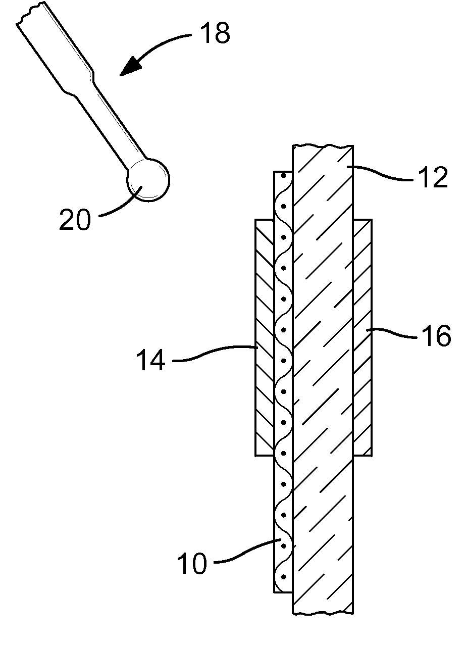
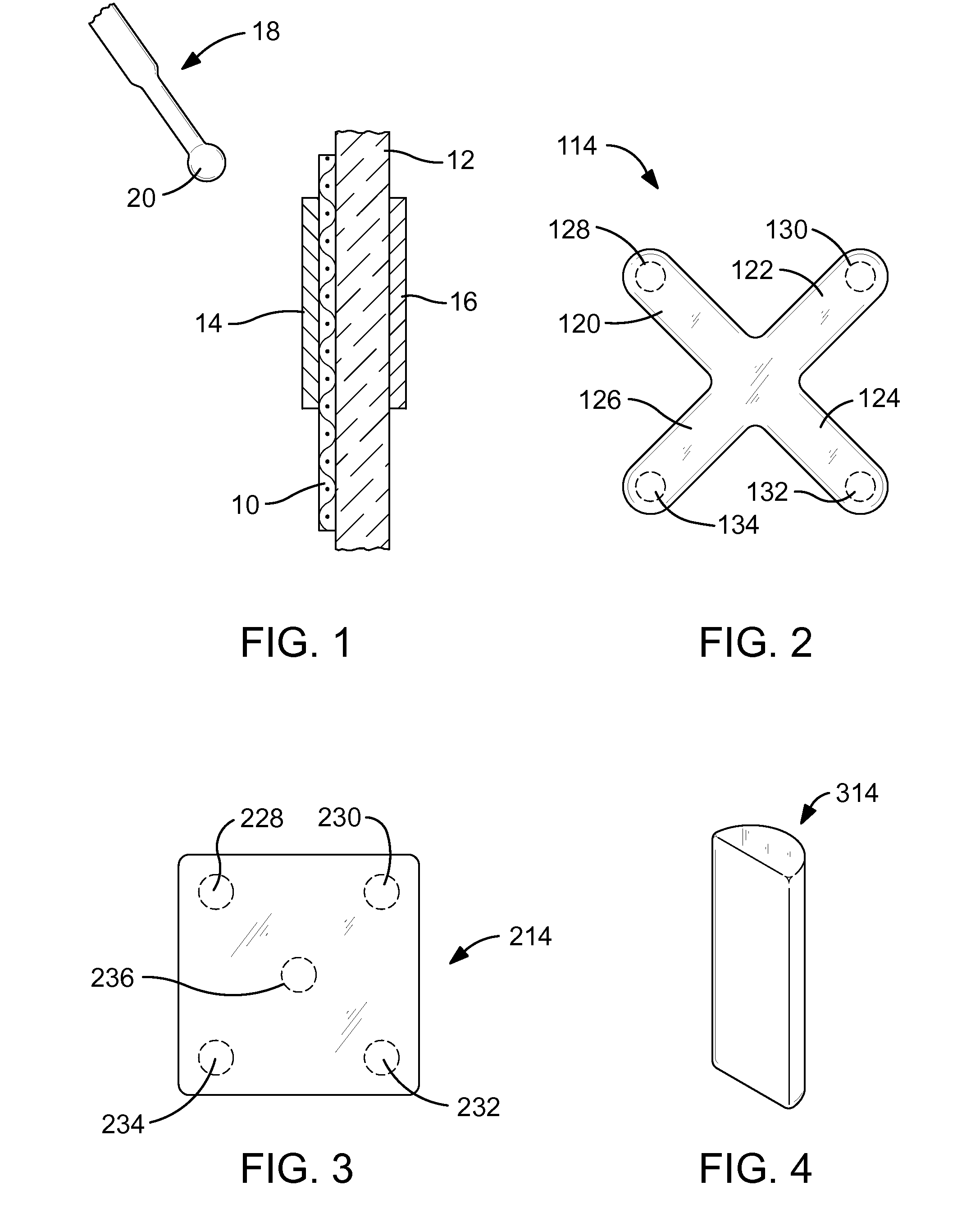
[0015]FIG. 1 of the drawings shows a surgical mesh 10 pinned against a body tissue 12, such as an abdominal wall, by a first magnetic material 14 and a second magnetic material 16. The first magnetic material 14 and the second magnetic material 16, one of which must be a magnet and the other of which may be either a magnet or merely magnetically responsive, have been inserted into place using conventional surgical tools such as a laparoscope (not shown). The surgical mesh 10 may be maneuvered into a final position relative to the body tissue 12 by other conventional surgical tools (not shown).

[0016]The advantage of using magnetic materials such as the first magnetic material 14 and the second magnetic material 16 is that repositioning of the surgical mesh is relatively easily accomplished. The first magnetic material 14 and the second magnetic material 16 are small enough to be readily delivered to the surgical site and removed therefrom by for example by a laparoscopic tool.

[0017]F...


PUM


Abstract

A method of appropriately positioning a surgical mesh relative to body tissue during surgery, using at least two magnets or alternatively, at least a magnet and a magnetically responsive material. The magnet or magnetically responsive materials are delivered to the surgical site for example through a laparoscope. A magnet or magnetically responsive material may be in sheet form and coiled or otherwise made compact to accommodate the laparoscope, then expanded to a final effective configuration. If the surgical mesh is not appropriately located relative to the body tissue, it may be appropriately repositioned by urging it using a tool, which may act by magnetic attraction, such that the mesh slides along the body tissue. The surgical mesh may then be fixed to body tissue using conventional surgical fasteners.

Description

FIELD OF THE INVENTION[0001]The present invention relates to manipulating a surgical mesh into appropriate positioning on a patient during surgery.BACKGROUND OF THE INVENTION[0002]Surgical mesh material must be accurately placed against tissues of a patient in the course of surgery, such as for example against the abdominal wall for laparoscopic ventral or incisional hernia repair. Ordinarily, in a minimally invasive procedure wherein only small instruments are used, meshes are manipulated with visual feedback provided by a video camera. Once positioned, the mesh may be secured in place by tacks, screws, and sutures. However, the environment of surgery wherein minimally invasive techniques are employed, is fraught with problems in manipulating surgical mesh materials. Notably, working space in the surgical environment is quite limited. The mesh may be relatively large and therefore more difficult to orient appropriately. The view from the video camera may be less than ideal due to a...

Claims


Application Information

Patent Timeline
Patent Type & Authority Applications(United States)
IPC IPC(8): A61B17/08
CPCA61B17/52A61B2017/00876A61F2/0063A61F2002/30079A61F2210/009
Inventor NEFF, MARC
Owner NEFF MARC
Why Eureka
Try Eureka