Flexible tools for preparing bony canals

a flexible, bony canal technology, applied in the field of medical procedures and tools, can solve the problems of force damage to the anterior, left, and right walls of the canal, and achieve the effect of avoiding the damage of the anterior, left, and right walls

Inactive Publication Date: 2010-05-06
BRAINSGATE LTD
View PDF52 Cites 79 Cited by
  • Summary
  • Abstract
  • Description
  • Claims
  • Application Information

AI Technical Summary

Benefits of technology

[0039]In some embodiments of the present invention, surgical tools and methods are provided for preparing a greater palatine canal to allow placement of an elongated neural stimulator in and / or through the canal. The stimulator is typically used to apply stimulation to the sphenopalatine ganglion (SPG), which is located at the distal end of the canal. The tools are configured to open a passage through the canal while minimizing the application of forces in directions perpendicular to the longitudinal axes of the tools. Such perpendicular forces could damage fragile anterior, left, and right walls of the canal. The tools typically open the passage through soft tissue within the canal, and / or between anatomical features of the canal, such as between soft tissue and the osseous wall of the canal. In some cases, the tools dilate the canal. The tools include a forward tool and an abrading tool.
[0040]In some embodiments of the present invention, a forward tool is configured to apply a forward longitudinal force in order to open the passage through the canal, substantially without applying forces to the walls of the canal in directions perpendicular to the longitudinal axis of the tool. The forward tool comprises a distal rod, a proximal shaft, and a resisting element. The distal rod is coupled to the proximal shaft such that the distal rod articulates with the proximal shaft with greater than one degree of freedom, such as in all directions (i.e., 360 degrees), while the resisting element is arranged to resist articulation of the distal rod with the proximal shaft. The distal rod is shaped so as to define a blunt distal tip that opens the passage the canal as the tip is advanced distally through the canal and applies the forward longitudinal force. The articulation minimizes the application of forces to the walls of the canal in directions perpendicular to the longitudinal axis of the distal rod, such as if the proximal shaft should become slightly misaligned with the direction of the canal. Typically, the resisting element couples the proximal shaft to the distal rod. The resisting element typically comprises an elastic element.
[0041]In some embodiments of the present invention, an abrading tool is configured to both apply a forward longitudinal force and abrade in a posterior direction, substantially without applying forces to the left and right walls of the canal perpendicular to the abrasion direction. The abrading tool comprises a distal rod, a proximal shaft, and a resisting element. The distal rod is coupled to the proximal shaft such that the distal rod articulates with the proximal shaft with exactly one degree of freedom. As a result, the distal rod articulates in the left and right directions, and is prevented from articulating in the posterior and anterior directions perpendicular to these two directions. The resisting element is arranged to resist articulation of the distal rod with the proximal shaft. A portion of the abrading tool facing in the posterior direction is shaped so as to define an abrading surface. This arrangement provides rigidity in the posterior direction for abrading, while providing flexibility in the left and right directions, thereby minimizing the application of forces to the left and right walls of the canal in respective directions perpendicular to the axis of the distal rod. Typically, the resisting element couples the proximal shaft to the distal rod. The resisting element typically comprises an elastic element.

Problems solved by technology

Such perpendicular forces could damage fragile anterior, left, and right walls of the canal.

Method used


Image

  • Flexible tools for preparing bony canals
  • Flexible tools for preparing bony canals
  • Flexible tools for preparing bony canals

Examples


Embodiment Construction

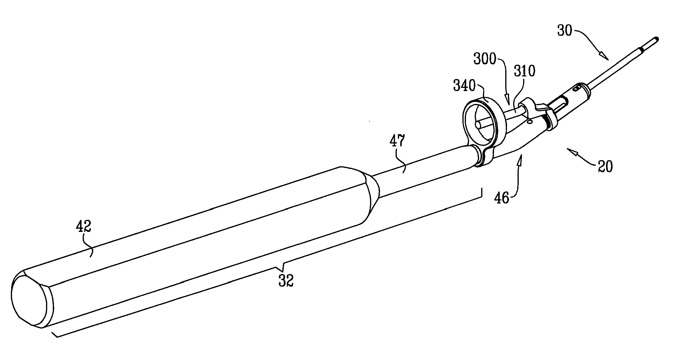
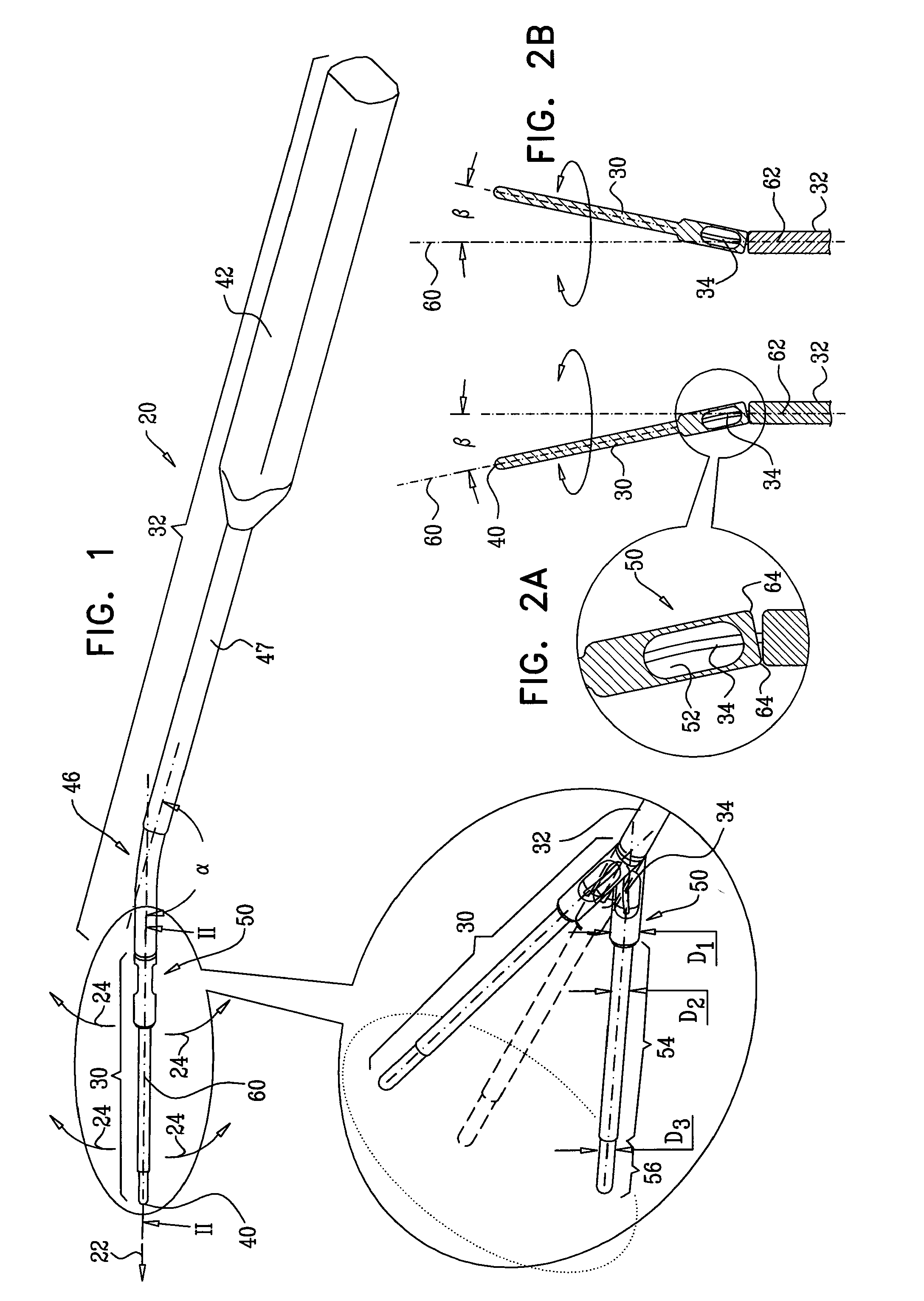
[0258]FIG. 1 is a schematic illustration of a forward tool 20 for preparing a bony canal, in accordance with an embodiment of the present invention. Forward tool 20 is configured to open a passage through the canal by applying a forward longitudinal force, schematically indicated by an arrow 22, substantially without applying forces to the walls of the canal in directions perpendicular to a central longitudinal rod axis 60 of distal rod 30. These directions are schematically indicated by arrows 24 in FIG. 1. The tool opens the passage through soft tissue within the canal, and / or between anatomical features of the canal, such as between soft tissue and the osseous wall of the canal.

[0259]Forward tool 20 comprises a distal rod 30, a proximal shaft 32, and a resisting element 34. Distal rod 30 is shaped so as to define a blunt distal tip 40 that opens the passage through the canal as the tip is advanced distally through the canal and applies a forward longitudinal force. For some appli...


PUM


Abstract

Apparatus is provided that includes a surgical tool, which includes a proximal shaft, a distal rod, and a target sight. A proximal end of the distal rod is coupled to a distal end of the proximal shaft such that the distal rod articulates with the proximal shaft. The target sight includes an aiming element, which is coupled to the distal rod and extends toward the proximal shaft, and which is indicative of an alignment of the distal rod with respect to the proximal shaft. Other embodiments are also described.

Description

CROSS-REFERENCE TO RELATED APPLICATIONS[0001]The present application claims the benefit of U.S. Provisional Application 61 / 195,556, filed Oct. 7, 2008, which is assigned to the assignee of the present application and is incorporated herein by reference.FIELD OF THE INVENTION[0002]The present invention relates generally to medical procedures and tools. More specifically, the invention relates to medical procedures and tools for preparing a bony canal for implantation therethrough of a medical device.BACKGROUND OF THE INVENTION[0003]The sphenopalatine ganglion (SPG) is a neuronal center located in the brain behind the nose. It consists of parasympathetic neurons innervating the middle cerebral and anterior cerebral lumens, the facial skin blood vessels, and the lacrimal glands. Activation of this ganglion is believed to cause vasodilation of these vessels. A second effect of such stimulation is the opening of pores in the vessel walls, causing plasma protein extravasation (PPE). This ...

Claims


Application Information

Patent Timeline
Patent Type & Authority Applications(United States)
IPC IPC(8): A61B17/56
CPCA61B17/1659A61B17/1688A61B17/24A61B17/320016A61B17/3403A61B17/3468A61B2017/320008A61B2017/32006A61B2017/3413A61N1/0546A61N1/0548A61N1/0551A61B2090/063A61B2034/2046A61B2034/2063A61B2090/064A61B2090/0807A61B2090/3929A61N1/372
Inventor DEGTYAR, LEONIDREICH, TAL
Owner BRAINSGATE LTD
Why Eureka
Try Eureka