
Control System for Working Machine

a control system and working machine technology, applied in the direction of electrical control, program control, instruments, etc., can solve the problem of large number of writable nonvolatile memories required

Active Publication Date: 2010-05-06
KUBOTA LTD
View PDF5 Cites 10 Cited by
  • Summary
  • Abstract
  • Description
  • Claims
  • Application Information

AI Technical Summary

Benefits of technology

[0007]The object of the present invention is to provide a control system which not only allows each one of the plurality of control units to control a controlled object assigned thereto appropriately, but allows simplification and cost reduction of the system through reduction in the number of writable nonvolatile memories.

Problems solved by technology

And, if a trouble develops in the detecting sensor or the actuator with use of the working machine, a maintenance operation is effected on this sensor or actuator.
However, since each one of the plurality of control units is equipped with the memory as described above, a large number of writable nonvolatile memories are required.

Method used


Image

  • Control System for Working Machine
  • Control System for Working Machine
  • Control System for Working Machine

Examples


Embodiment Construction

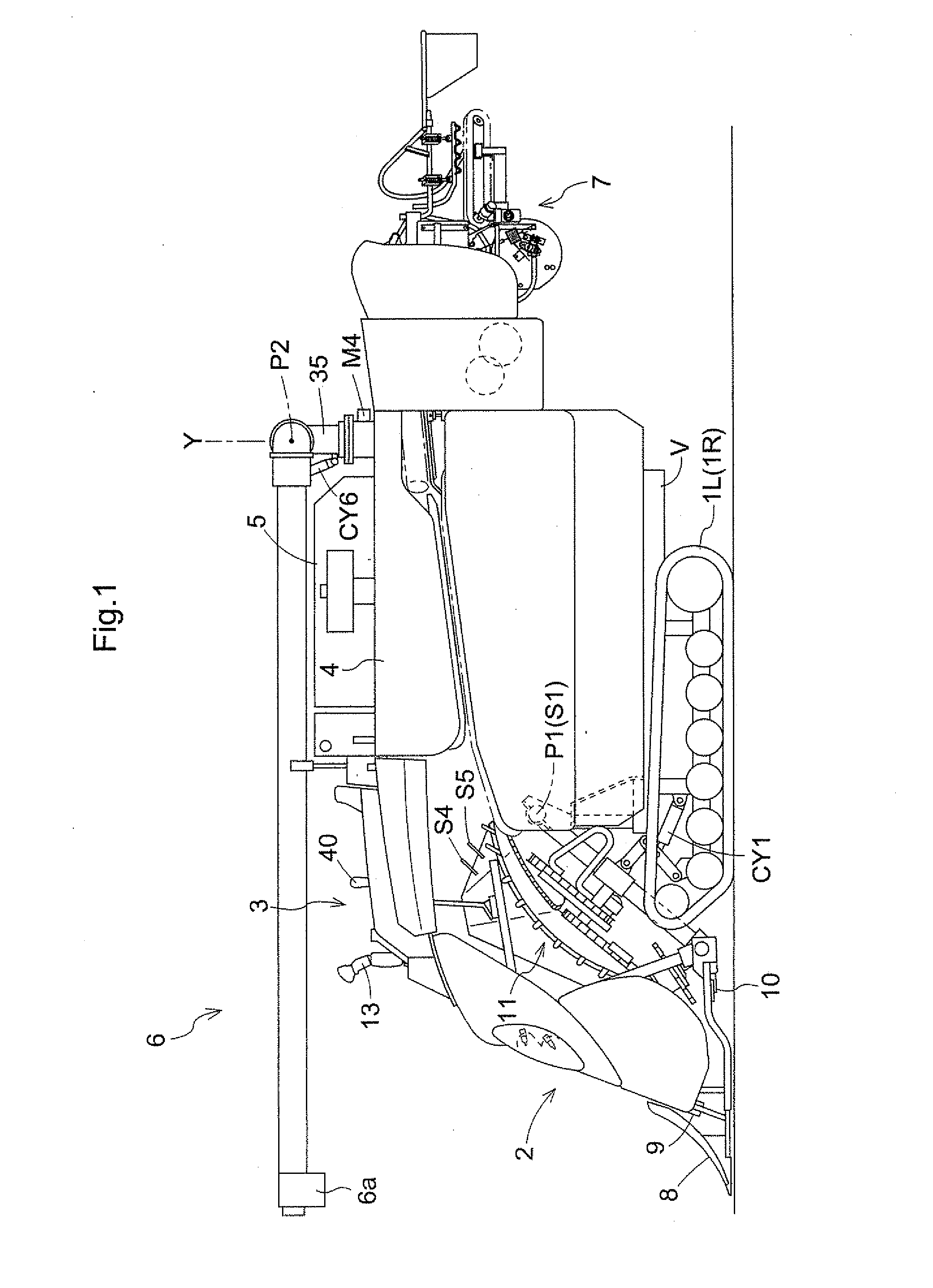
[0092]Next, with reference to the accompanying drawings, there will be described an embodiment in which the control system of the invention is applied to a combine as an example of the working machine.

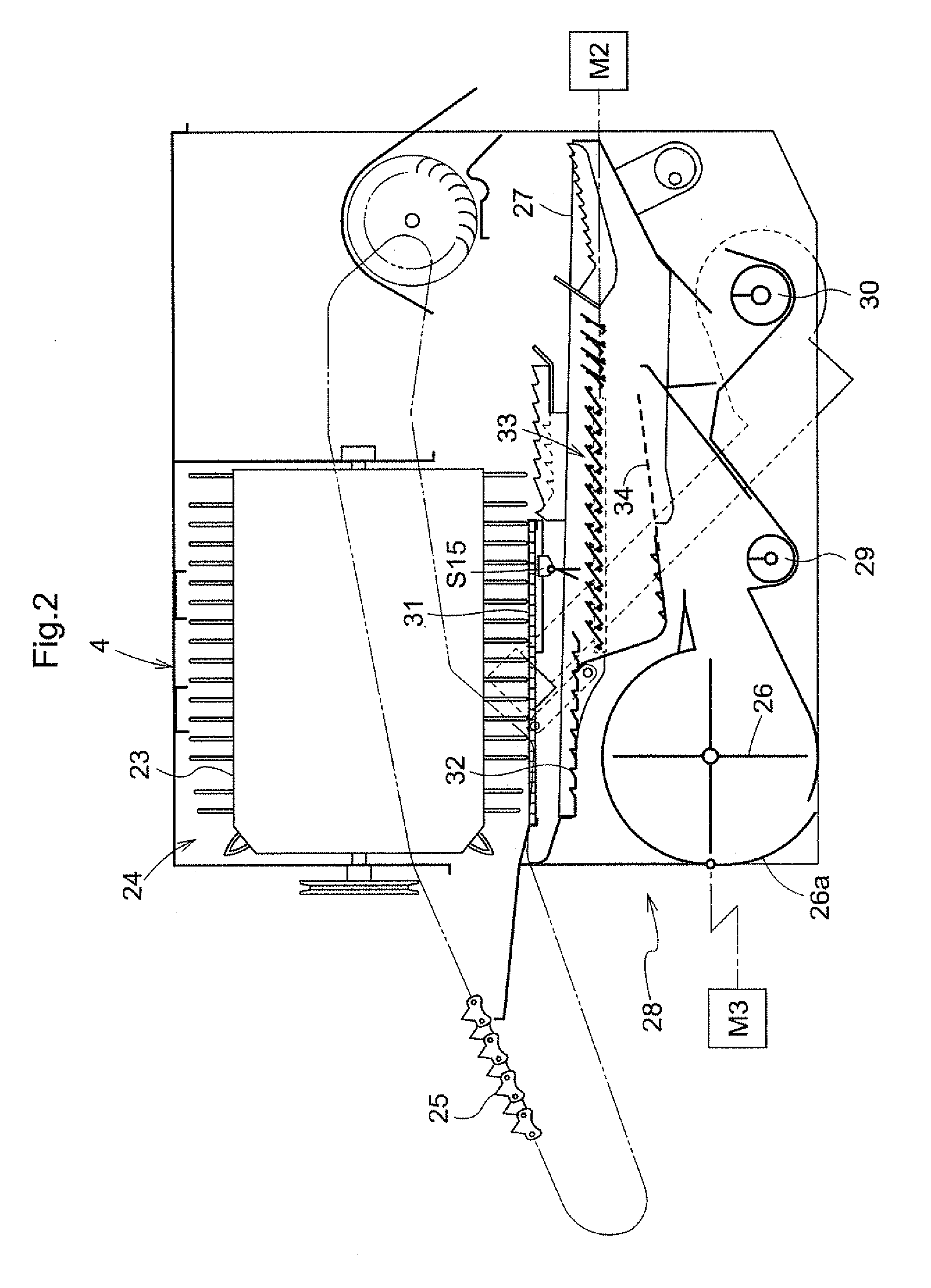
[0093]As shown in FIG. 1, in this combine, to a front portion of a machine body V having a pair of right and left crawler type traveling devices 1R, 1L, there is attached a harvesting section 2, with this section 2 being vertically pivotable about a horizontal axis P1 by means of a harvesting lift cylinder CY1 as an actuator. Rearwardly of this harvesting section 2, there are mounted an operational section 3, a threshing section 4 for threshing / sorting harvested culms, a grain tank 5 for reserving therein grains to be fed from the threshing section 4, a grain discharging unloader 6 for discharging the grains from within the grain tank 5, a bundling device 7 for bundling waste straws after the threshing by a predetermined amount and discharging the bundled straws to the outside of the m...


PUM


Abstract

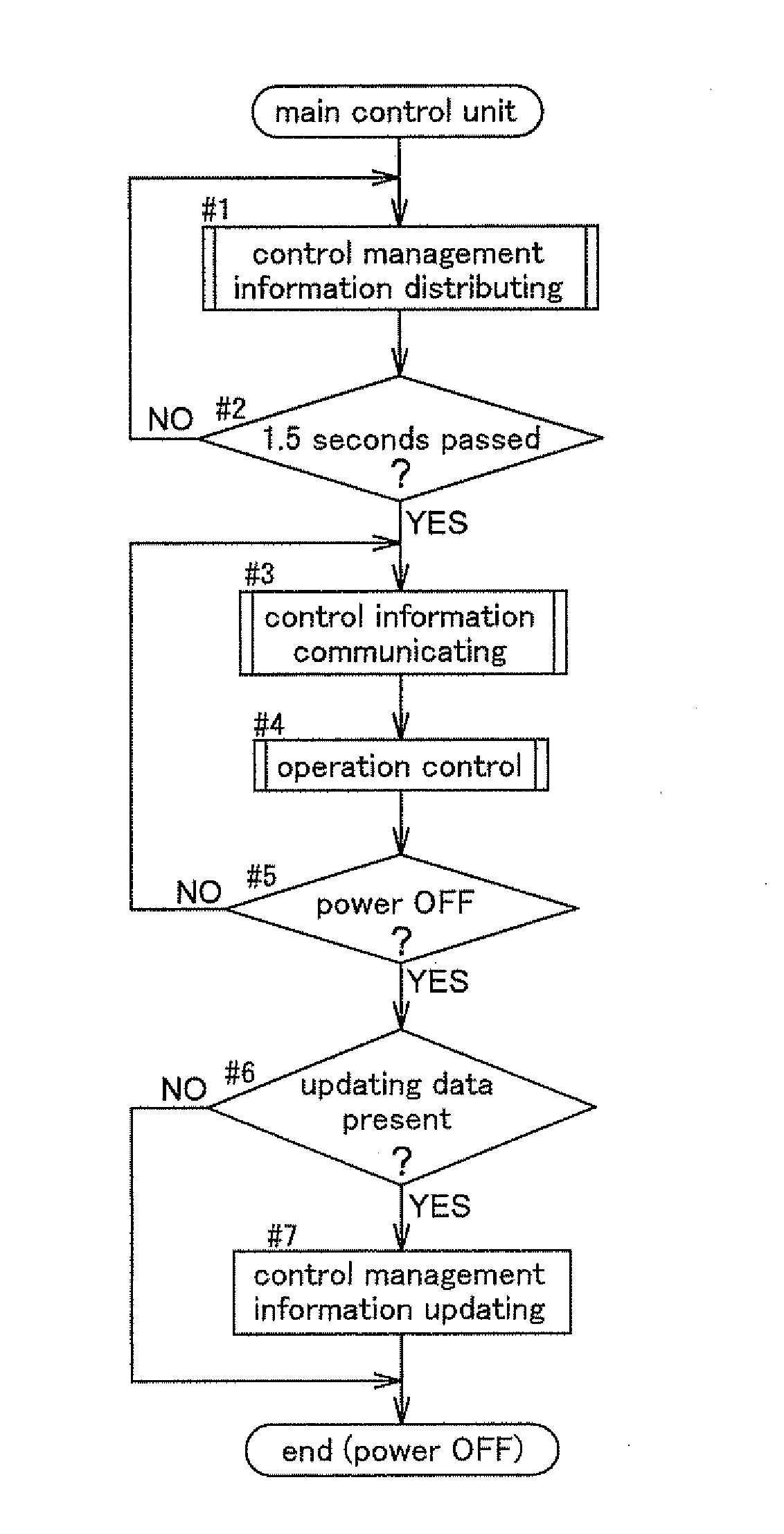
A plurality of control units capable of communicating with each other via a data communication network (TU) are disposed in distribution. One of the plurality of control units is set as an information management control unit (H1) having writable nonvolatile storing means. Upon activation with power supply thereof, the information management control unit (H1) executes a control management information distributing process for transmitting control management information stored in a memory (50) to storage object control units (H2-H6) via the communication network (TU). Upon activation with power supply thereto, each of the storage object control units (H2-H6) executes a control management information obtaining process for obtaining the control management information transmitted from the control management information control unit (HI).

Description

TECHNICAL FIELD[0001]The present invention relates to a control system for a working machine comprising: a plurality of control units disposed in distribution to be capable of communicating with each other via a data communication network, each one of the plurality of control units controlling a controlled object assigned thereto, based upon input information inputted by information inputting means included in this unit, control information communicated from a further control unit, and control management information.BACKGROUND ART[0002]With the above-described control system for a working machine, each one of the plurality of control units controls a controlled object assigned thereto. Various kinds of information such as the input information inputted by the information inputting means provided in one control unit and information indicative of a control condition of the controlled object can be utilized for controlling in a further control unit. And, such information is transmitted...

Claims


Application Information

Patent Timeline
IPC IPC(8): G05B19/042G06F17/00
CPCA01B79/005A01D41/1274F02D29/02G05B2219/25072G05B2219/25094A01D41/127F02D45/00A01D41/02
Inventor FUJII, YASUONAKAJIMA, TETSUYANAKA, TAMAKIHAYASHI, SHIGEKIYAMANAKA, YUKIFUMI
Owner KUBOTA LTD
Learn More