System for power facility navigation

a technology for navigation systems and power facilities, applied in navigation instruments, traffic control systems, instruments, etc., can solve the problems of inactive development of navigation systems specific to electric power systems, large amount of attribute information difficulty in handling a large number of spatial objects of power distribution systems, etc., to improve customer service quality, shorten dispatch time and recovery time, and improve the effect of customer service quality

Inactive Publication Date: 2010-05-06
KOREA ELECTRIC POWER CORP
View PDF14 Cites 37 Cited by
  • Summary
  • Abstract
  • Description
  • Claims
  • Application Information

AI Technical Summary

Benefits of technology

[0025]In a feature of the present invention, the power facility navigation system provides functions for identification of a destination location and transit location and for road navigation, and helps to quickly dispatch a field service technician to the destination location, shortening the failure recovery time and enhancing the customer service.
[0027]Hence, the power facility navigation system enables instant handling of customer service tasks and shortening of dispatch time and recovery time, and contributes to rapid handling of customer service requests and enhancement of customer service quality along with effective operation of the call center.

Problems solved by technology

However, most commercially available products employ private data formats without standardization and provide services in static formats on the basis of national base maps, and hence may have difficulty in handling a vast number of spatial objects of power distribution systems and a large amount of attribute information of power facilities.
As the domestic market for navigation in Korea reaches over six millions in number, development of navigation systems specific to electric power systems is not active because of a relatively small market.
As described above, although the demand is recognized for a power facility navigation system supporting rapid dispatch, failure recovery and facility maintenance, development thereof has been at a standstill owing to difficulty of technology development and limited market size.

Method used


Image

  • System for power facility navigation
  • System for power facility navigation
  • System for power facility navigation

Examples


Embodiment Construction

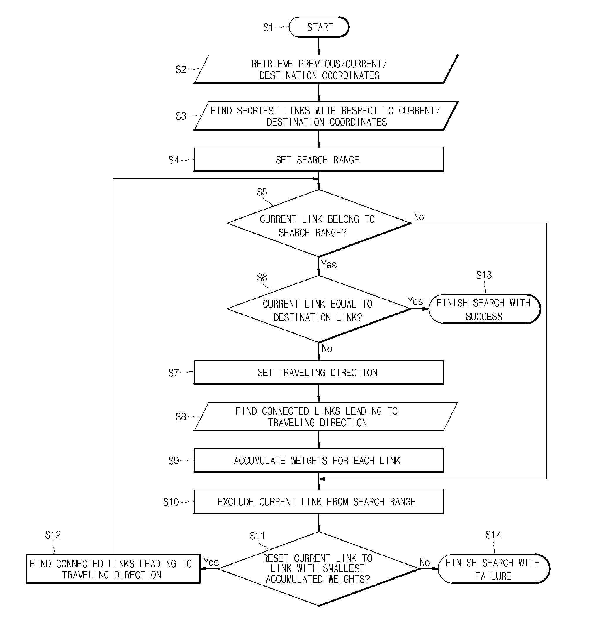
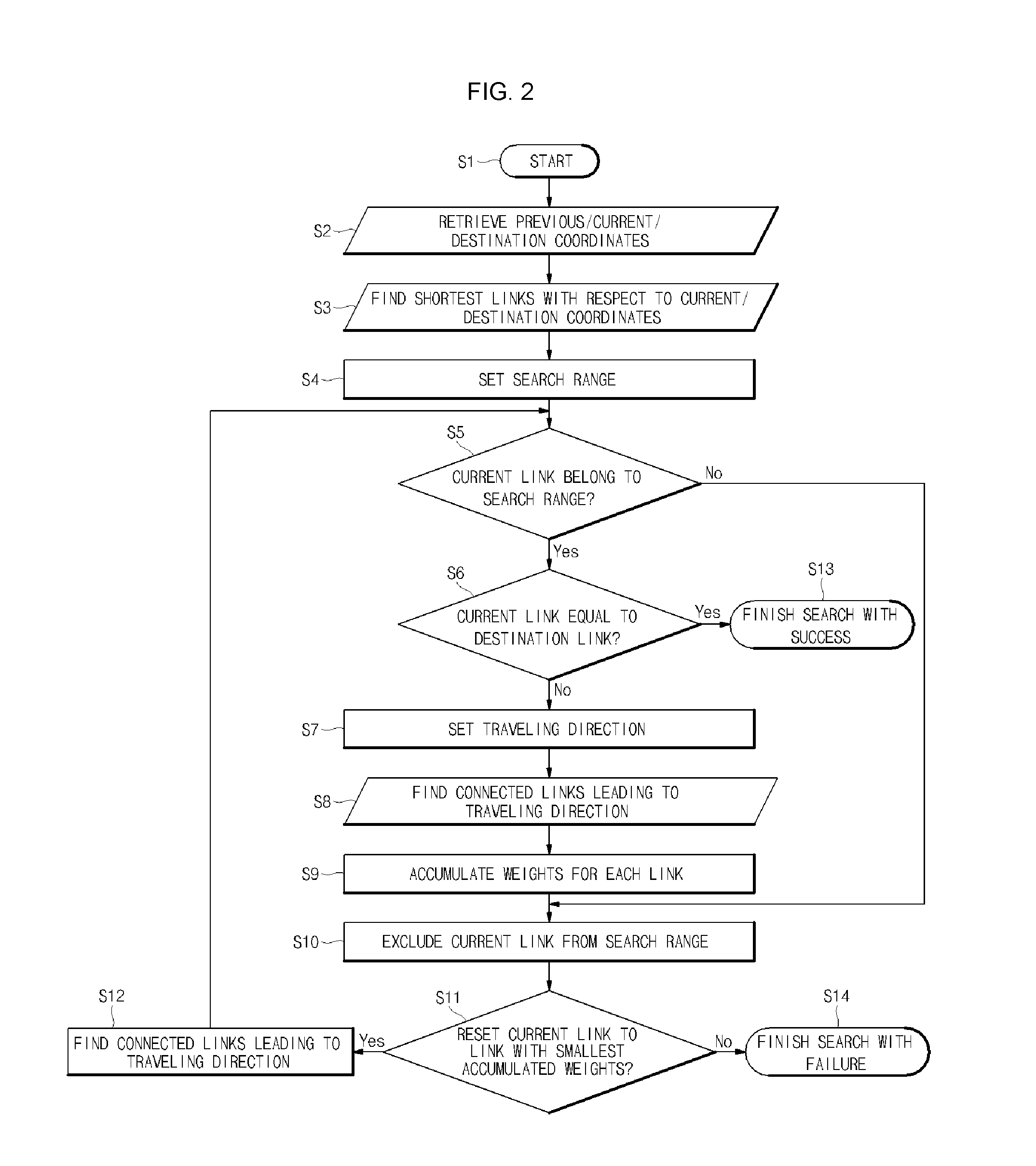
[0035]Hereinafter, embodiments of the present invention are described in detail with reference to the accompanying drawings. The same reference symbols are used throughout the drawings to refer to the same or like parts. Detailed descriptions of well-known functions and structures incorporated herein may be omitted to avoid obscuring the subject matter of the present invention.

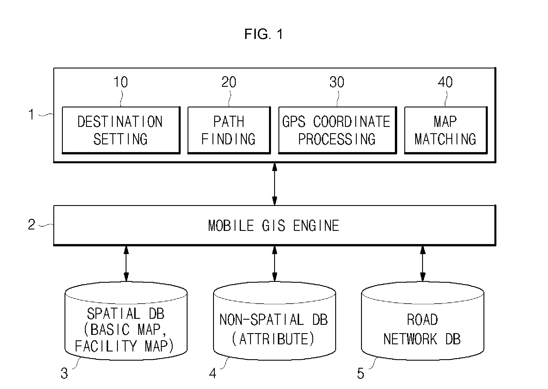
[0036]FIG. 1 illustrates a configuration of a power facility navigation system according to an embodiment of the present invention. Referring to FIG. 1, the power facility navigation system includes a power facility navigation processor 1, mobile GIS engine 2, spatial database 3 containing basic maps and facility maps, non-spatial database 4, and road network database 5.

[0037]In the spatial database 3, facility maps includes information regarding 26 types of power facilities necessary for power facility navigation and field service handling, such as electric poles, transformers, switches, and overhead / undergro...


PUM


Abstract

A system for power facility navigation is disclosed. For rapid dispatch in the field service including power failure recovery and maintenance, the destination location can be set using various items such as pole numbers, computerization codes, customer names, trade names, equipment numbers and GIS coordinates. Destination location setting and path finding can be performed in order of priorities assigned to these items and in consideration of characteristics of field service activities. Location coordinates are received through a GPS receiver, coordinate conversion is performed according to a facility GIS coordinate system, and map matching is processed when GPS coordinates do not match facility GIS coordinates. The road network database is composed of linear array structures and the structure of a link is configured to include information regarding all other links connected to the start node and end node in a manner that link information and node attributes are integrated together.

Description

BACKGROUND OF THE INVENTION[0001]1. Field of the Invention[0002]The present invention relates to a power facility navigation system that, for rapid dispatch in a power system field service such as failure recovery or maintenance, sets a destination location using computerization codes of power facilities, electric pole numbers, customer names, trade names, addresses, numbers, equipment numbers and facility GIS coordinates, and performs a path-finding operation to guide a field technician in motion to the destination location to thereby shorten dispatch time, failure recovery time and customer power outage time, and enhance the customer support service. Further, the power facility navigation system enables fast path-finding on the basis of a basic map and facility map with a mobile terminal device having a limited capacity and performance, and interworks with a wireless communication network so that various field service activities can be handled in real time in the field.[0003]2. De...

Claims


Application Information

Patent Timeline
Patent Type & Authority Applications(United States)
IPC IPC(8): G01C21/36
CPCG01C21/30G01C21/3605G06Q10/047G01C21/3453G01S19/01G08G1/096894
Inventor SHIN, JIN HOKIM, YOUNG ILLEE, BONG JAESONG, JAE JU
Owner KOREA ELECTRIC POWER CORP
Why Eureka
Try Eureka