
System for dynamic program profiling

a program profiling and program technology, applied in the field of high-performance computing systems, can solve the problems of large amount of memory and a large amount of time to complete the process, inefficient portions of the program may be improved, and simulators may not accurately capture the dynamic behavior of the application executing on a particular hardware system

Inactive Publication Date: 2010-05-06
GLOBALFOUNDRIES INC
View PDF59 Cites 41 Cited by
  • Summary
  • Abstract
  • Description
  • Claims
  • Application Information

AI Technical Summary

Benefits of technology

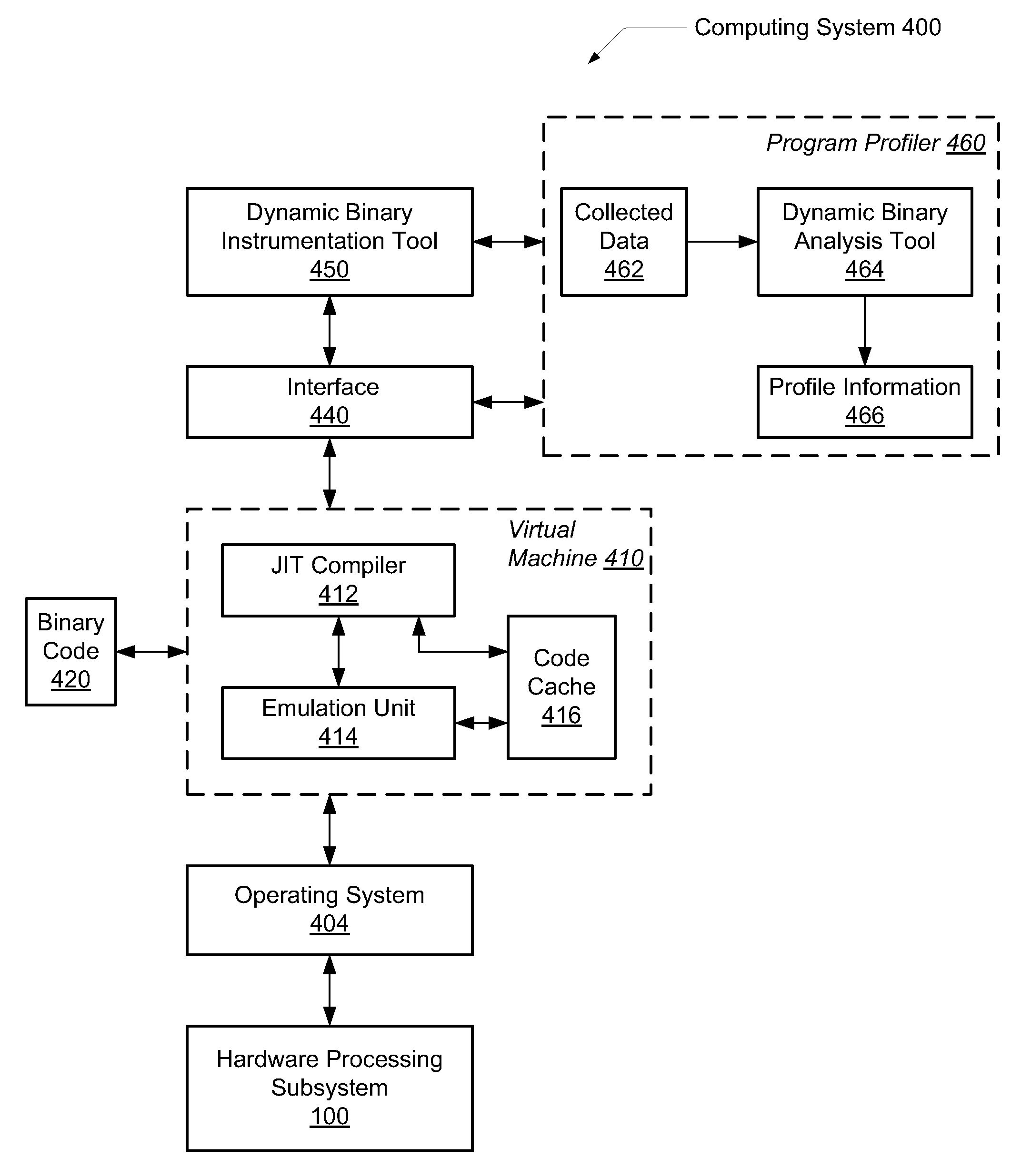
The patent describes a system and method for profiling software applications by analyzing the code they run. This is done by adding extra code to the code during translation and execution, which captures information about how the code is being executed. This information is then used to create a profile of the application that accurately describes its behavior. This can be useful for identifying areas of the code that are being executed frequently, which can help improve performance and identify areas that need improvement.

Problems solved by technology

Inefficient portions of the program may be improved once the inefficiencies are known.
This approach requires a large amount of memory and a large amount of time to complete the process.
Further, a simulator may not accurately capture the dynamic behavior of the application executing on a particular hardware system (e.g., since the simulator may be operating on statistical data).
However, many current path profiling techniques only capture acyclic paths.
Without tools to efficiently identify expensive inter-procedural paths, it is difficult to improve the performance of software.
However, these approaches do not capture whole program profiling of the application.
Further, as processor speeds have increased, it has become more difficult to collect complete execution traces for applications.
This is in part due to the sheer number of instructions in such a trace, and also in part due to the performance overhead required to capture these traces.

Method used


Image

  • System for dynamic program profiling
  • System for dynamic program profiling
  • System for dynamic program profiling

Examples


Embodiment Construction

[0020]In the following description, numerous specific details are set forth to provide a thorough understanding of the present invention. However, one having ordinary skill in the art should recognize that the invention may be practiced without these specific details. In some instances, well-known circuits, structures, and techniques have not been shown in detail to avoid obscuring the present invention.

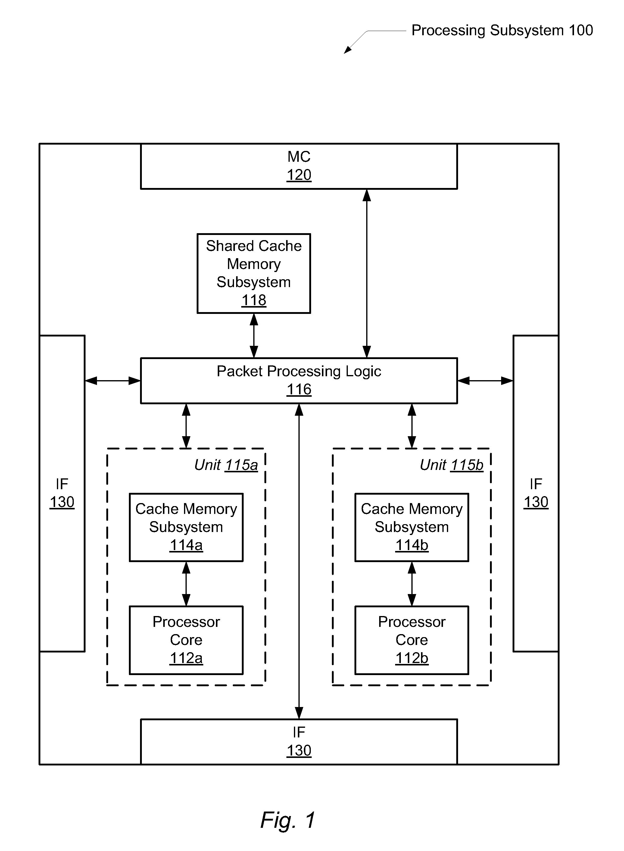
[0021]FIG. 1 is a block diagram of one embodiment of an exemplary processing subsystem 100. Processing subsystem 100 may include memory controller 120, interface logic 140, one or more processing units 115, which may include one or more processor cores 112 and a corresponding cache memory subsystems 114; packet processing logic 116, and a shared cache memory subsystem 118. Processing subsystem 100 may be a node within a multi-node computing system. In one embodiment, the illustrated functionality of processing subsystem 100 is incorporated upon a single integrated circuit.

[0022]Proce...


PUM


Abstract

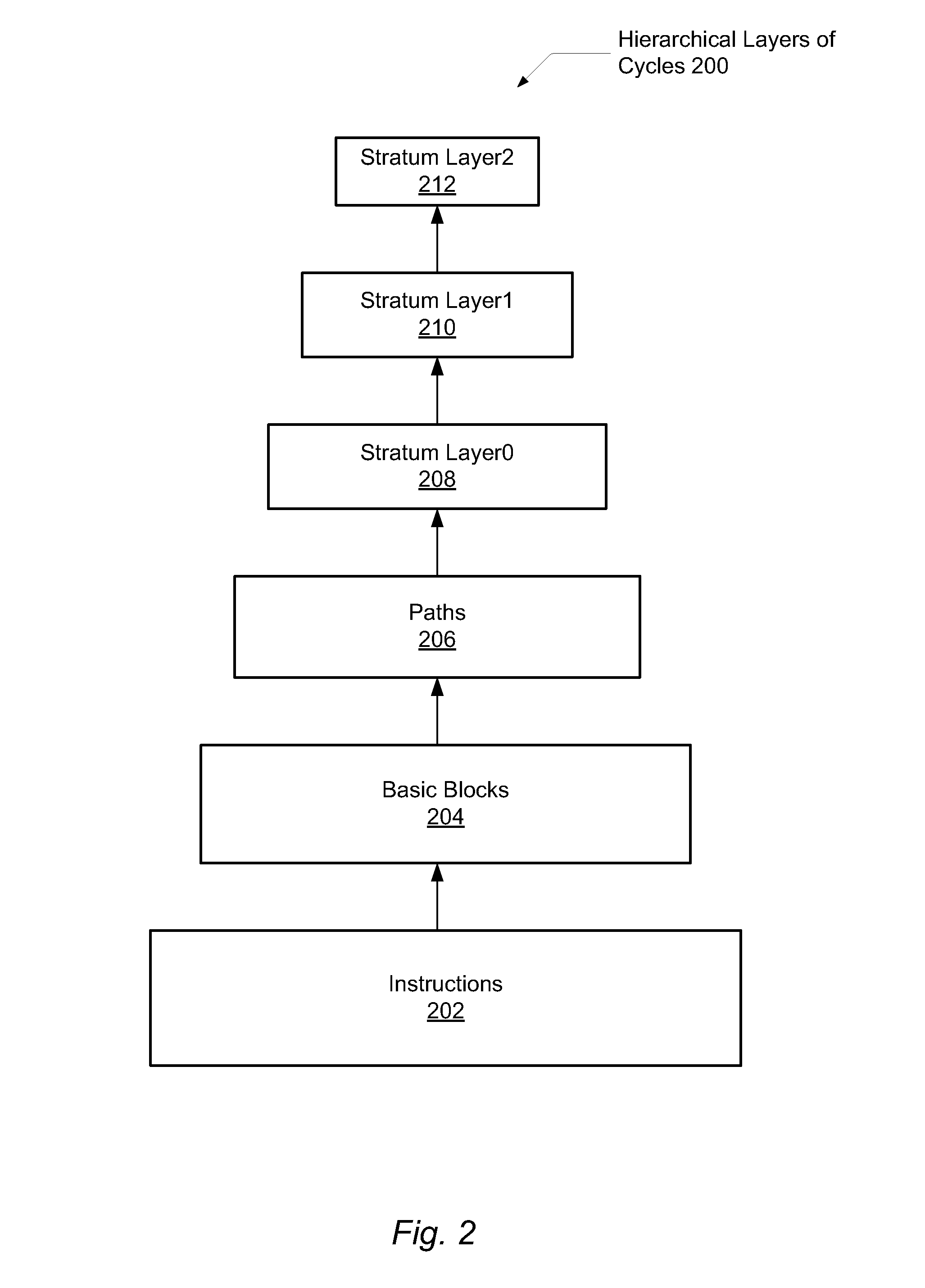
A system and method for efficient whole program profiling of software applications. A computing system comprises a dynamic binary instrumentation (DBI) tool coupled to a virtual machine configured to translate and execute binary code of a software application. The binary code is augmented with instrumentation and analysis code during translation and execution. Characterization information of each basic block is stored as each basic block is executed. A dynamic binary analysis (DBA) tool inspects this information to identify hierarchical layers of cycles within the application that describe the dynamic behavior of the application. A sequence of basic blocks may describe paths, a sequence of paths may describe a stratum, and a sequence of strata may describe a stratum layer. Statistics of these layers and hot paths may be determined and stored. This data storage yields a whole program profile comprising program phase changes that accurately describes the dynamic behavior of the application.

Description

BACKGROUND OF THE INVENTION[0001]1. Field of the Invention[0002]This invention relates to high performance computing systems, and more particularly, to maintaining and performing efficient whole program profiling of software applications.[0003]2. Description of the Relevant Art[0004]Software programmers write applications to perform work according to an algorithm or a method. The program's performance may be increased based on an understanding of the dynamic behavior of the entire program. Inefficient portions of the program may be improved once the inefficiencies are known. The following program information may aid in describing a program's dynamic behavior such as code coverage, call-graph generation, memory-leak detection, instruction profiling, thread profiling, race detection, or other. In addition, understanding a program's dynamic behavior may be useful in computer architecture research such as trace generation, branch prediction techniques, cache memory subsystem modeling, f...

Claims


Application Information

Patent Timeline
Patent Type & Authority Applications(United States)
IPC IPC(8): G06F9/44
CPCG06F11/3452G06F11/3466G06F11/3644G06F2201/865G06F9/4552
Inventor GORTON, JR., RICHARD C.
Owner GLOBALFOUNDRIES INC
Learn More