Tractor And Baler Interaction System

a technology which is applied in the field of tractor and baler interaction system, can solve the problems of engine overreacting and overshooting, reducing the power take-off speed, and ineffective timing of power,

Active Publication Date: 2010-05-13
DEERE & CO
View PDF8 Cites 15 Cited by
  • Summary
  • Abstract
  • Description
  • Claims
  • Application Information

AI Technical Summary

Benefits of technology

[0006]The invention in one form is directed to an agricultural power control system including a moving element, a power source, a signal generating element and a torque modifying device. The moving element is configured to engage a quantity of crop material in a cyclical manner. The power source conveys power to the moving element. The signal generating element is configured to provide a signal relating to an anticipated quantity of crop material prior to the moving element engaging the quantity of crop material. The torque modifying device is configured to cause the power source to alter an amount of torque delivered to the moving element dependent upon the signal.

Problems solved by technology

As the plunger compresses the material, it causes a reduction in the power take-off speed due to the increased load.
The problem with this increased power output is that it lags the power requirement thereby causing the engine to overreact and overshoot after each load of the cycle of the plunger has been completed.
However, this method along with others has been ineffective in addressing the timing of the power production with the need for the power during the cyclical operation of the baler.

Method used


Image

  • Tractor And Baler Interaction System
  • Tractor And Baler Interaction System
  • Tractor And Baler Interaction System

Examples


Embodiment Construction

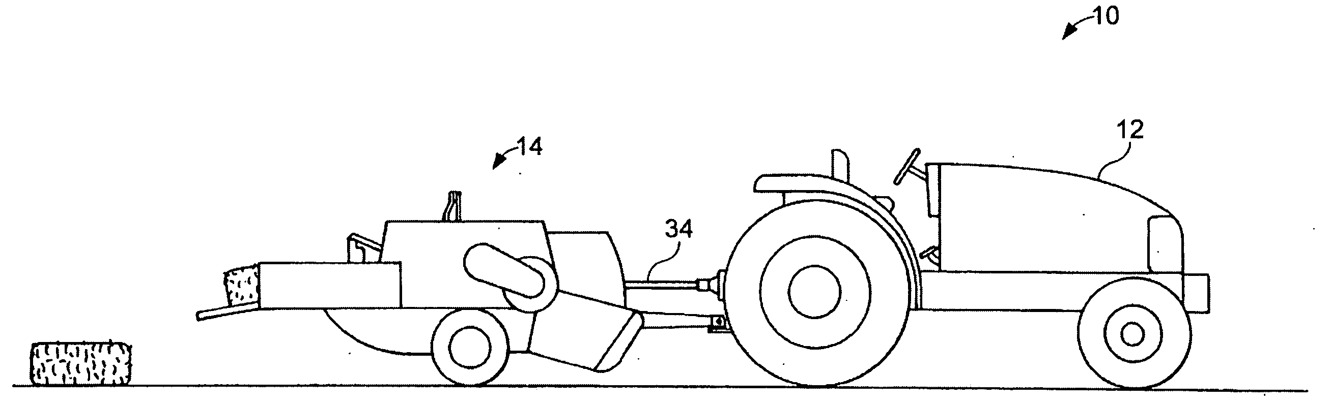
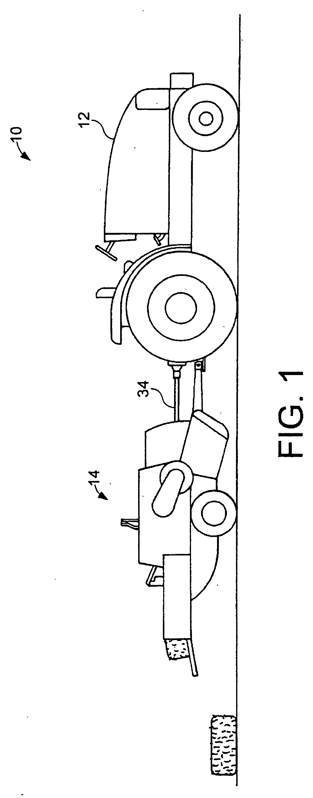
[0012]Referring now to the drawings, and more particularly to FIG. 1, there is illustrated a power control system 10 including a tractor 12 and a baler 14. Baler 14 is hitched to tractor 12 and a power take off (PTO) shaft 16 supplies power from tractor 12 to baler 14. As tractor 12 pulls baler 14 and baler 14 encounters crop material, crop material is fed into the baler and the crop material is processed into bales.

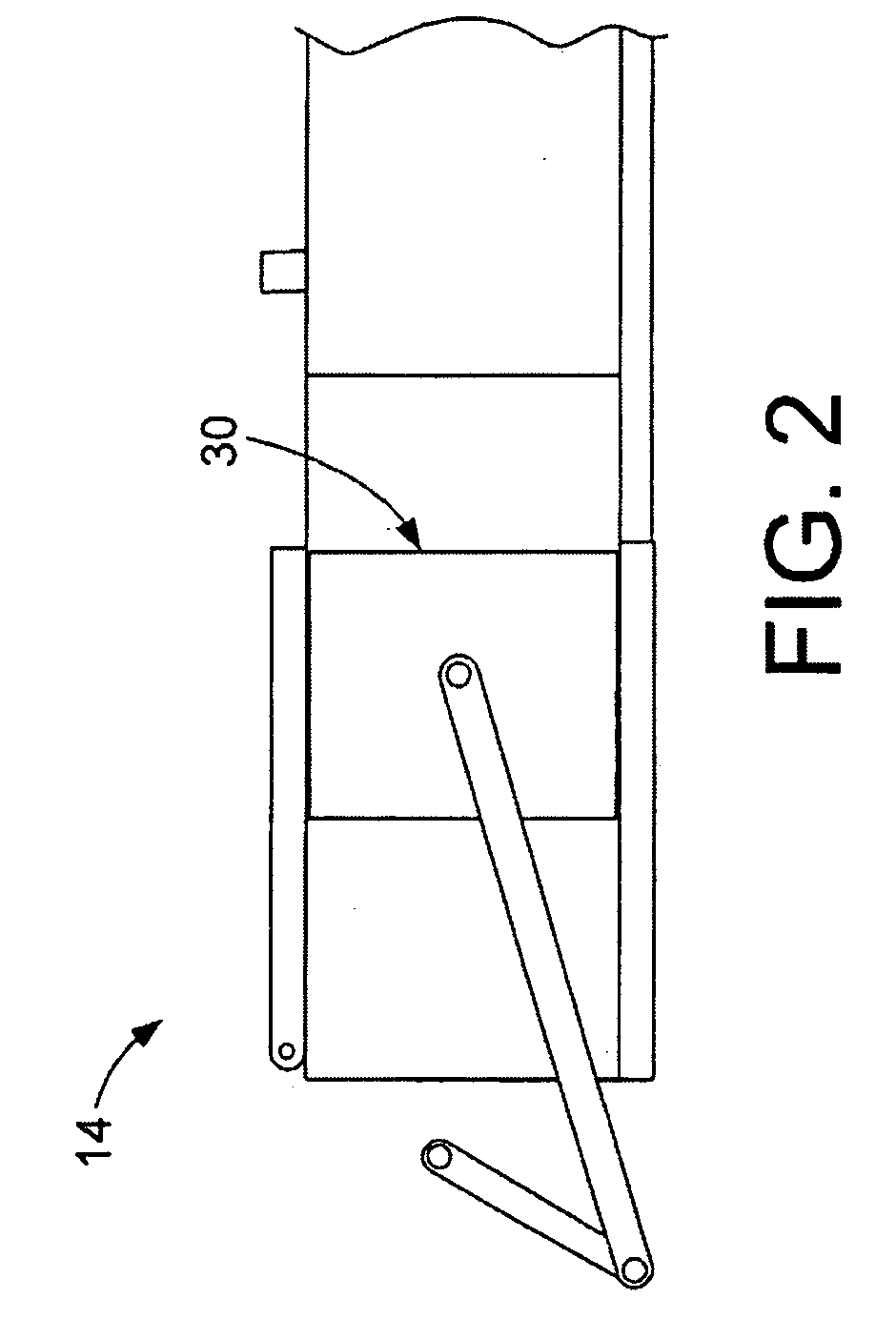
[0013]Now, additionally referring to FIGS. 2 and 3, there is illustrated a side view of baler 14 having a reciprocating plunger therein. As crop material is pulled into the plunging section of baler 14, the PTO RPM begins to reduce as the load is encountered by the plunger as illustrated in FIG. 3. This reduction in the PTO RPM is detected by mechanisms contained in tractor 12 and the reduced RPM of the engine that is reflective of the reducing PTO RPM is compensated for by an increase in the fuel supply to the engine there by causing the overshoot, again illustrated in ...


PUM


Abstract

An agricultural power control system including a moving element, a power source, a signal generating element and a torque modifying device. The moving element is configured to engage a quantity of crop material in a cyclical manner. The power source conveys power to the moving element. The signal generating element is configured to provide a signal relating to an anticipated quantity of crop material prior to the moving element engaging the quantity of crop material. The torque modifying device is configured to cause the power source to alter an amount of torque delivered to the moving element dependent upon the signal.

Description

BACKGROUND OF THE INVENTION[0001]The present invention relates to a tractor and baler system, and, more particularly, to an engine output modification system associated with a tractor / baler system.DESCRIPTION OF THE RELATED ART[0002]A plunger type hay baler includes a frame that is hitched to a tractor and is configured to receive crop material, such as hay or straw, into a pressing channel in which the crop material is pressed and formed into a bale. The baler includes a loading mechanism in which the crop material is collected from the ground and is then routed into the pressing channel in a manner that is synchronous with a plunger that moves in the pressing channel. As the plunger moves in a reciprocating manner in the pressing channel, each new flake of crop material is moved into the channel and is compacted into the bale. After a sufficient amount of crop material has been compressed, a twine threading mechanism inserts a twine through a portion of the compressed material and...

Claims


Application Information

Patent Timeline
Patent Type & Authority Applications(United States)
IPC IPC(8): A01D69/00A01F15/00A01D75/00A01F15/08
CPCA01D41/1274A01F15/04A01F15/0841
Inventor SCHLESSER, WALTER MARKLANG, ERIC RYANROVEY, JASON
Owner DEERE & CO
Why Eureka
Try Eureka