
Water heater

a water heater and water tank technology, applied in the field of water heaters, can solve the problems of long time, water consumption and fuel gas consumption, and achieve the effects of accurate reduction of the flow rate of flowing water, and reducing the flow ra

Active Publication Date: 2010-05-13
PALOMA IND LTD
View PDF7 Cites 21 Cited by
  • Summary
  • Abstract
  • Description
  • Claims
  • Application Information

AI Technical Summary

Benefits of technology

[0007]The present invention is to provide a water heater capable of shortening a time required to reach the preset temperature even at a time of the cold start, and thus saving water and gas.
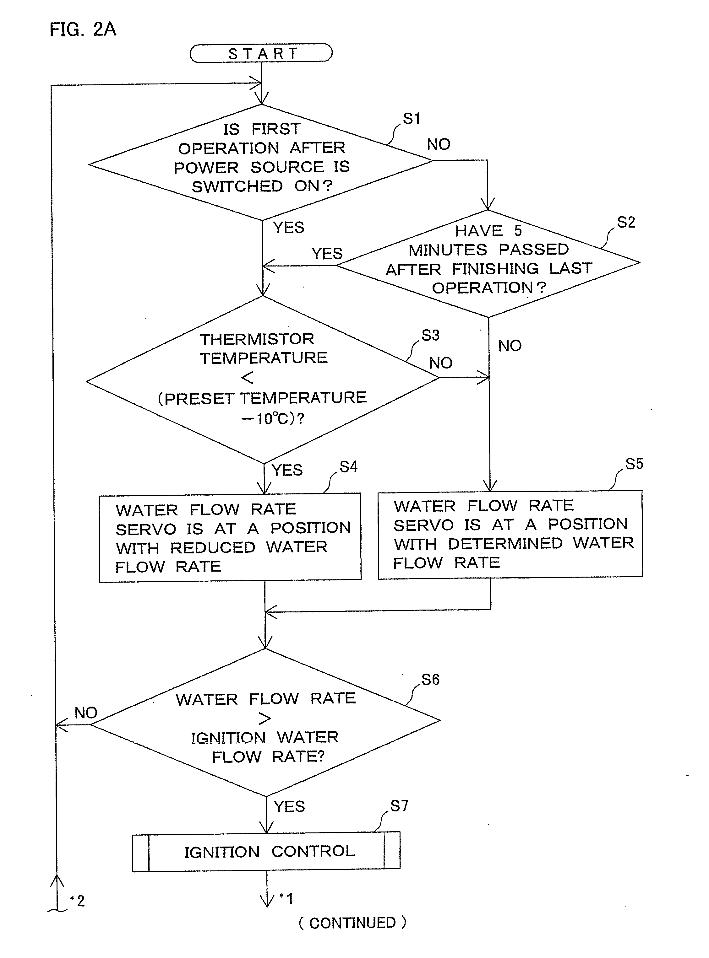
[0012]According to a fourth aspect of the present invention, in order to accurately reduce the flow rate of flowing water only at a time of a cold start in any one of the first to third aspects, the operation control unit compares the detected temperature at the time of non-operation with the preset temperature, and keeps the water flow rate control unit standing by when a certain period of time elapses after finishing the last operation.
[0013]According to the first aspect of the present invention, in the case where a water temperature in a heat exchanger is low at the time of non-operation, the flow rate of flowing water of the water flow rate control unit is kept standing by with a reduced flow rate and a control of discharged hot water at a time of starting of the operation is performed with the reduced flow rate. Thus, even in the case where the cold start is made, a time required to reach the preset temperature can be shortened, thereby resulting in saving water and gas.
[0014]According to the second and third aspects of the present invention, in addition to the effect of the first aspect, a temperature control of normal discharged hot water can be performed with a sufficient flow rate of flowing water.
[0015]According to the fourth aspect of the present invention, the operation control unit compares the detected temperature at the time of non-operation with the preset temperature and the water flow rate control unit is kept standing by when a predetermined period of time elapses after finishing the last operation. Therefore, in addition to the effect of any one of the first to third aspects, the flow rate of flowing water can be accurately reduced only at a time of the cold start and not be reduced in a state of high heat capacity of a heat exchanger.

Problems solved by technology

Thus, in the case where a temperature of flowing water is low, or so-called cold start where an operation of the water heater is started by switching on a power source at a first time after installing the device or is started when a long time elapses after the last hot water supplying, it takes a long time for the temperature of discharged hot water to reach a preset temperature and consumptions of water and fuel gas during that time become high, which leads to loss.

Method used


Image

  • Water heater
  • Water heater
  • Water heater

Examples


Embodiment Construction

[0020]Embodiments of the present invention will be described below referring to drawings.

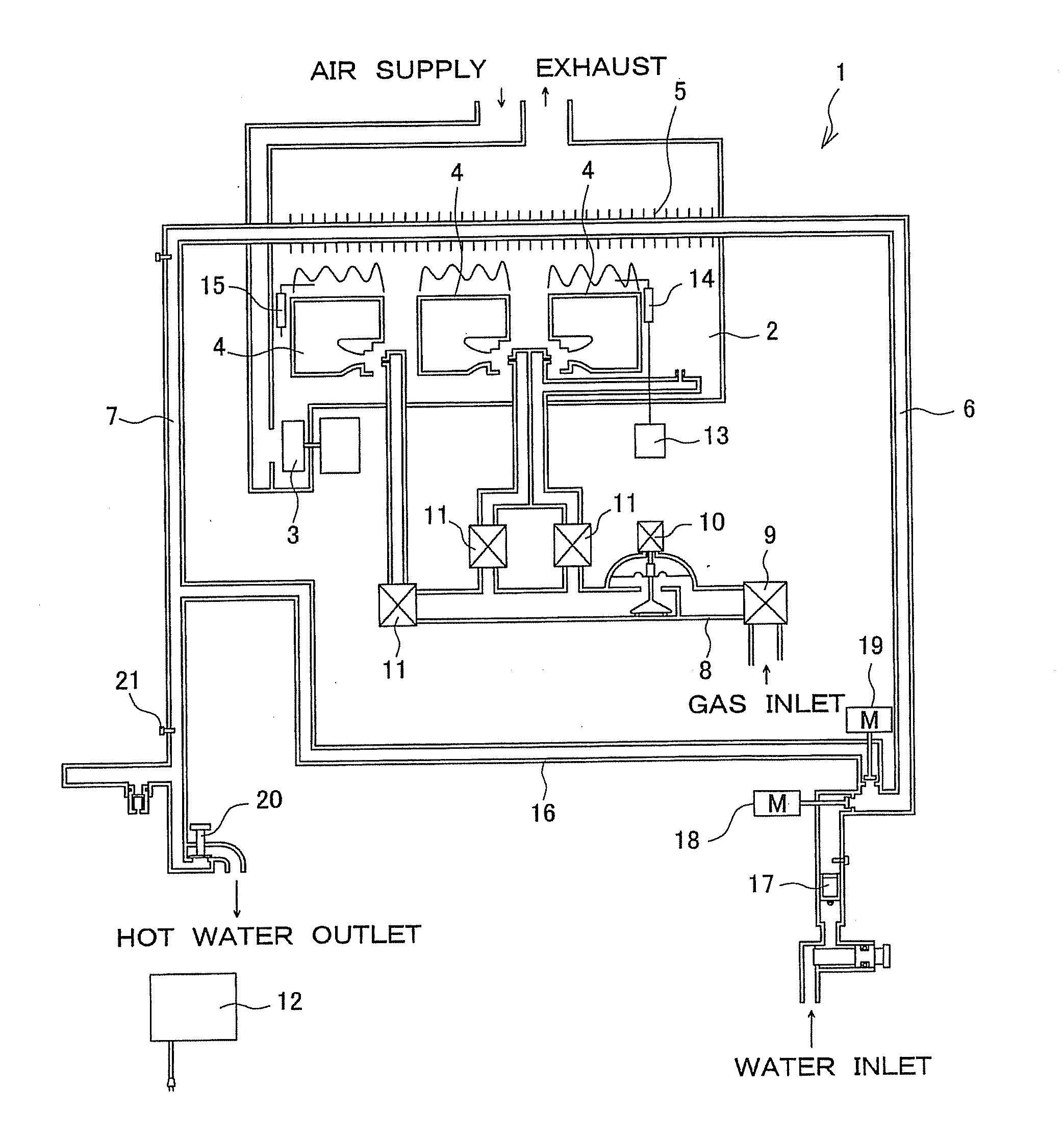
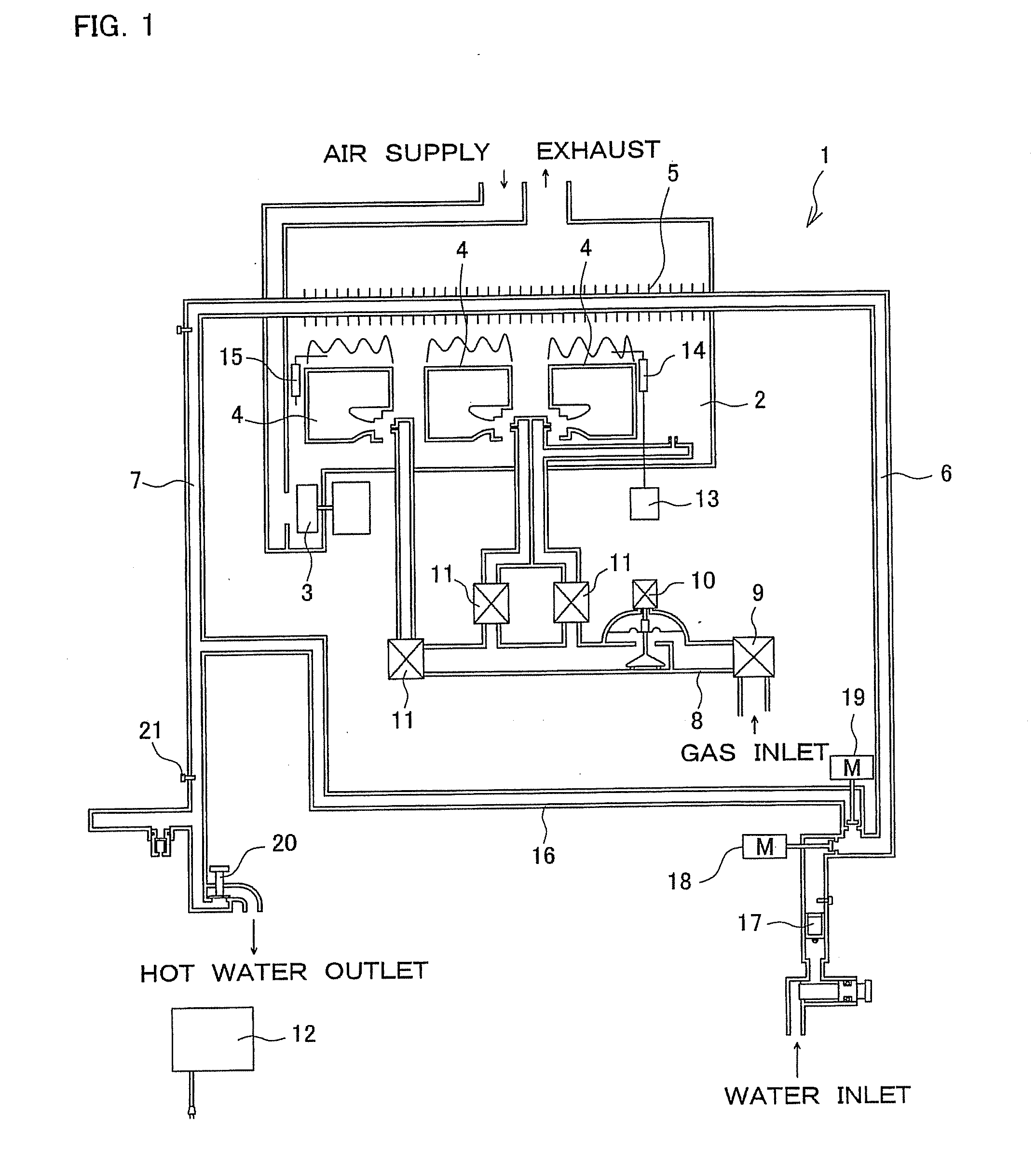
[0021]FIG. 1 is a schematic view for illustrating one example of a water heater. A water heater 1 includes a combustion chamber 2 having an air supply fan 3 in a water heater main body. The combustion chamber 2 is provided with, in its inside, a plurality of burners 4, 4, . . . (3 units in this case) for combusting mixed gas of fuel gas and primary air from the air supply fan 3, and a heat exchanger 5 heated by combustion of the burner 4, the heat exchanger 5 being connected with a water supplying pipe 6 and a hot-water discharging pipe 7. A main solenoid valve 9 and a gas proportional valve 10 are provided in a gas pipe 8 connected to the burner 4, and changeover solenoid valves 11, 11, . . . are provided in each branch pipe branched from the gas pipe 8 and connected to each burner 4. Each valve can be controlled by a controller 12 serving as an operation control unit. The water heater 1 also i...


PUM


Abstract

In a non-operation state, a controller determines whether the first operation was made after a power source being switched on in S1, and determines whether 5 minutes has passed after finishing the last operation in S2. When the first operation was not made or 5 minutes have lapsed after the last operation, the controller determines whether a difference between a detected temperature acquired by a thermistor and a preset temperature is more than 10° C. in S3. When a temperature difference is more than 10° C., a water flow rate servo is made to stand by at a position with a flow rate of flowing water reduced to less than a determined flow rate by a predetermined amount in S4. When a hot water faucet is opened in this standing by state, a temperature control of discharged hot water at the time of starting of an operation (S8) is performed with the reduced flow rate of flowing water.

Description

BACKGROUND OF THE INVENTION[0001]This application claims the benefit of Japanese Patent Application Numbers 2008-289148 which were filed on Nov. 11, 2008, the entirety of which is incorporated by reference.[0002]1. Field of the Invention[0003]The present invention relates to a water heater having a water flow rate control unit for controlling a flow rate of flowing water in a heat exchanger.[0004]2. Description of the Background Art[0005]In a water heater, a water supplying pipe and a hot-water discharging pipe are connected with a heat exchanger heated by a burner. When a faucet is opened and water is passed into the device, a controller (an operation control unit) detects passing water and operates the burner to heat the water passing through the heat exchanger. Then, the heated water is discharged from the hot-water discharging pipe. Japanese Unexamined Patent Publication No. 2008-57845 discloses a water heater including a water flow rate control unit such as a water flow rate se...

Claims


Application Information

Patent Timeline
Patent Type & Authority Applications(United States)
IPC IPC(8): F24H9/20
CPCF24D19/1051F24D2220/0264F24D2220/044F24H9/2035F24H15/31F24H15/219F24H15/175F24H15/325F24H15/238F24H15/365F24H15/345
Inventor TSUJI, YOSHIKATSUYAMANE, ATSUSHI
Owner PALOMA IND LTD
Learn More