Cooking medium systems having a single fill manifold, and methods of supplying a cooking medium using such systems
Active Publication Date: 2010-05-13
HENNY PENNY
View PDF12 Cites 23 Cited by
Summary
Abstract
Description
Claims
Application Information
AI Technical Summary
This helps you quickly interpret patents by identifying the three key elements:
Problems solved by technology
Method used
Benefits of technology
[0013]In an embodiment of the invention, a system for delivering a cooking medium of a cooking apparatus comprises at least one cooking vessel, a drain manifold configured to be in fluid communication with the at least one cooking vessel, a fill manifold comprising an input valve and a plurality of output valves, wherein each of the plurality of output valves places the fill manifold in fluid communication with a corresponding one of the at least one cooking vessel, a first flow path connected to the input valve of the fill manifold, a filter container configured to selectively be in fluid communication with the fill manifold via the first flow path, a filter pump positioned between the filter container and the fill manifold and configured to selectively be in fluid communication with the fill manifold via the first flow path, and to convey a recycled, e.g., a filtered, cooking medium, an overflow pump configured to selectively be in fluid communication with the fill manifold via a second flow path and at least one portion of the first flow path, and to convey a new cooking medium to the fill manifold, and a controller configured to control the first fluid flow path to selective
Problems solved by technology
This plurality of multiple manifolds and structures, e.g., piping, actuators, solenoids, and controllers, used to operate and regulate the manifolds, may add complexity to the fryer design.
Nevertheless, when this cooking medium is returned to the frypot, the filtering process may reduce the amount of cooking medium remaining in the frypot.
If the amount of cooking medium drops below a predetermined level, then food that is cooked in the frypot may not be cooked completely or consistently, and the quality of food cooked in the
Method used
Image
Click on the blue label to locate the original text in one second.
Reading with bidirectional positioning of images and text.
Examples
Embodiment Construction
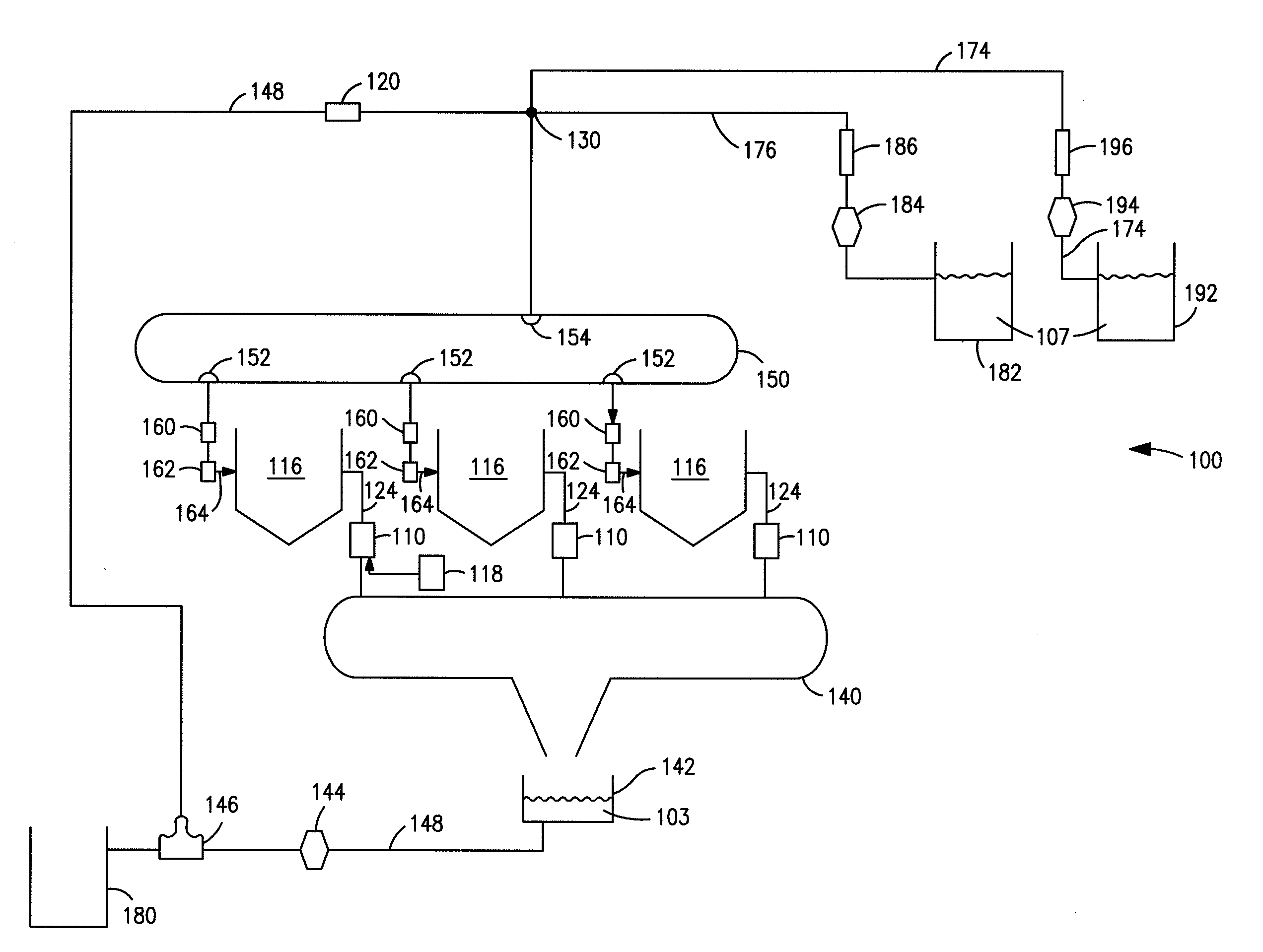
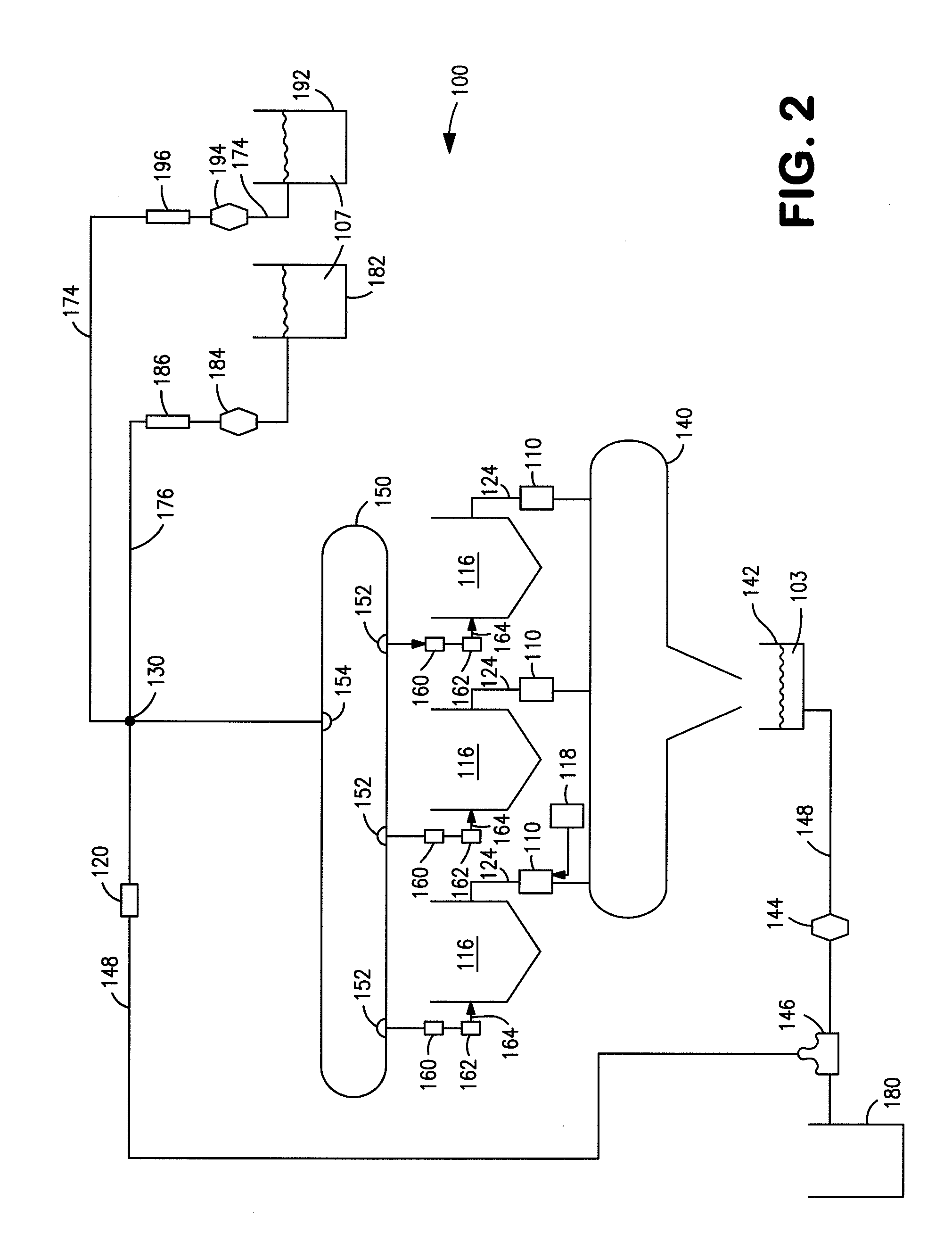
[0020]Preferred embodiments of the present invention, and their features and advantages, may be understood by referring to FIGS. 2-3, like numerals being used for corresponding parts in the various drawings.
[0021]FIG. 2 shows a cooking medium system, such as a fryer apparatus 100, according to an embodiment of the present invention. Fryer apparatus 100 may comprise at least one cooking vessel 116, e.g., a frypot, which may be configured to hold a cooking medium, e.g., an oil, a liquid shortening, a meltable-solid shortening, or the like. Cooking vessel 116 may have an opening 114 for receiving a food product. A heating element (not shown), e.g., a heating oil medium, a gas jet, or the like, may be positioned within cooking vessel 116. The heating element may apply heat to the cooking medium within vessel 116 until the cooking medium reaches a predetermined temperature, and also may apply heat to maintain the cooking medium within vessel 116 at a predetermined temperature. Fryer appa...
PUM
Abstract
A system for delivering a cooking medium of a cooking apparatus includes one or more cooking vessels. The system also includes a drain manifold in fluid communication with the cooking vessel, and a fill manifold having input valves, and output valves in fluid communication with a corresponding cooking vessel. A first flow path is connected to the fill manifold. A filter container selectively is in fluid communication with the fill manifold. A filter pump is positioned between the filter container and the fill manifold and conveys a recycled cooking medium. An overflow pump selectively is in fluid communication with the fill manifold via a second flow path and a portion of the first flow path. The overflow pump conveys a new cooking medium to the fill manifold. The first flow path conveys one of the recycled cooking medium and the new cooking medium to the fill manifold.
Description
CROSS-REFERENCE TO RELATED APPLICATIONS[0001]This application claims the benefit of U.S. Provisional Application No. 61 / 103,891, filed Oct. 8, 2008. Moreover, the disclosures of Patent Publication Nos. US 2008 / 0121115 A1 and US 2008 / 0121578 A1 are herby incorporated by reference in their entirety.BACKGROUND OF THE INVENTION[0002]1. Field of the Invention[0003]The present invention relates generally to systems and methods for automatically filtering a cooking medium in a cooking apparatus, such as a fryer.[0004]2. Description of Related Art[0005]Known fryers, e.g., open-well fryers and pressure fryers, are used to cook various food products, e.g., poultry, fish, potato products, and the like. Such fryers may include one or more cooking vessels, e.g., fryer pots, which may be filled with a cooking medium, e.g., an oil, a liquid shortening, or a meltable-solid shortening. Such fryers also include a heating element, e.g., an electrical heating element, such as a heating oil medium, or a...
Claims
Application Information
Patent Timeline
Application Date:The date an application was filed.
Publication Date:The date a patent or application was officially published.
First Publication Date:The earliest publication date of a patent with the same application number.
Issue Date:Publication date of the patent grant document.
PCT Entry Date:The Entry date of PCT National Phase.
Estimated Expiry Date:The statutory expiry date of a patent right according to the Patent Law, and it is the longest term of protection that the patent right can achieve without the termination of the patent right due to other reasons(Term extension factor has been taken into account ).
Invalid Date:Actual expiry date is based on effective date or publication date of legal transaction data of invalid patent.