Surface figure test method for large convex optical surfaces

a technology of optical surfaces and surface figures, applied in the direction of reflection surface testing, instruments, measurement devices, etc., can solve the problems of reducing the complexity and cost of the test setup, reducing the requirement for large-scale ancillary optics, and reducing the complexity and size of the test setup. , to achieve the effect of reducing complexity and size, reducing the cost of fabrication, and reducing the cost of production

Inactive Publication Date: 2013-11-05
MCKECHNIE THOMAS STEWART
View PDF3 Cites 2 Cited by
  • Summary
  • Abstract
  • Description
  • Claims
  • Application Information

AI Technical Summary

Benefits of technology

[0009]A method of testing the surface figure of a convex mirror (spherical or aspheric) is described that allows a significant reduction in the complexity and size of the ancillary test optics, making their fabrication simpler and less expensive. Ancillary optics diameters, whether null lenses or computer generated holograms, are typically 10× smaller than the diameter of the convex mirror under test. The convex mirror, referred to as the test optic, is fabricated from a substrate material that is transmissive at the chosen test wavelength. The rear surface of the test optic is polished and figured to some convenient but not necessarily precise shape, generally concave spherical for ease of testing. The front surface of the substrate is shaped and polished to approximately the desired convex curvature. The test optic can then be tested as though it were a lens. Using this test method any refractive index inhomogeneity of the substrate material will not affect the final figure accuracy of the front convex surface. This is the surface that will ultimately be coated with a reflective material to produce the desired convex mirror.

Problems solved by technology

Again, this lens has to have a diameter greater than the diameter of the mirror under test 31, further adding to the complexity and cost of the test setup.
The Hindle-Simpson test is not easily or cheaply implemented because of the large diameter requirements for the Hindle-Sphere—a meniscus element, and a calibration mirror—a concave spherical mirror.
Therefore, this approach does not eliminate the requirement for large expensive ancillary optics.

Method used


Image

  • Surface figure test method for large convex optical surfaces
  • Surface figure test method for large convex optical surfaces
  • Surface figure test method for large convex optical surfaces

Examples


case 1

Case 1: Using Test Setups #1, #2, and #3

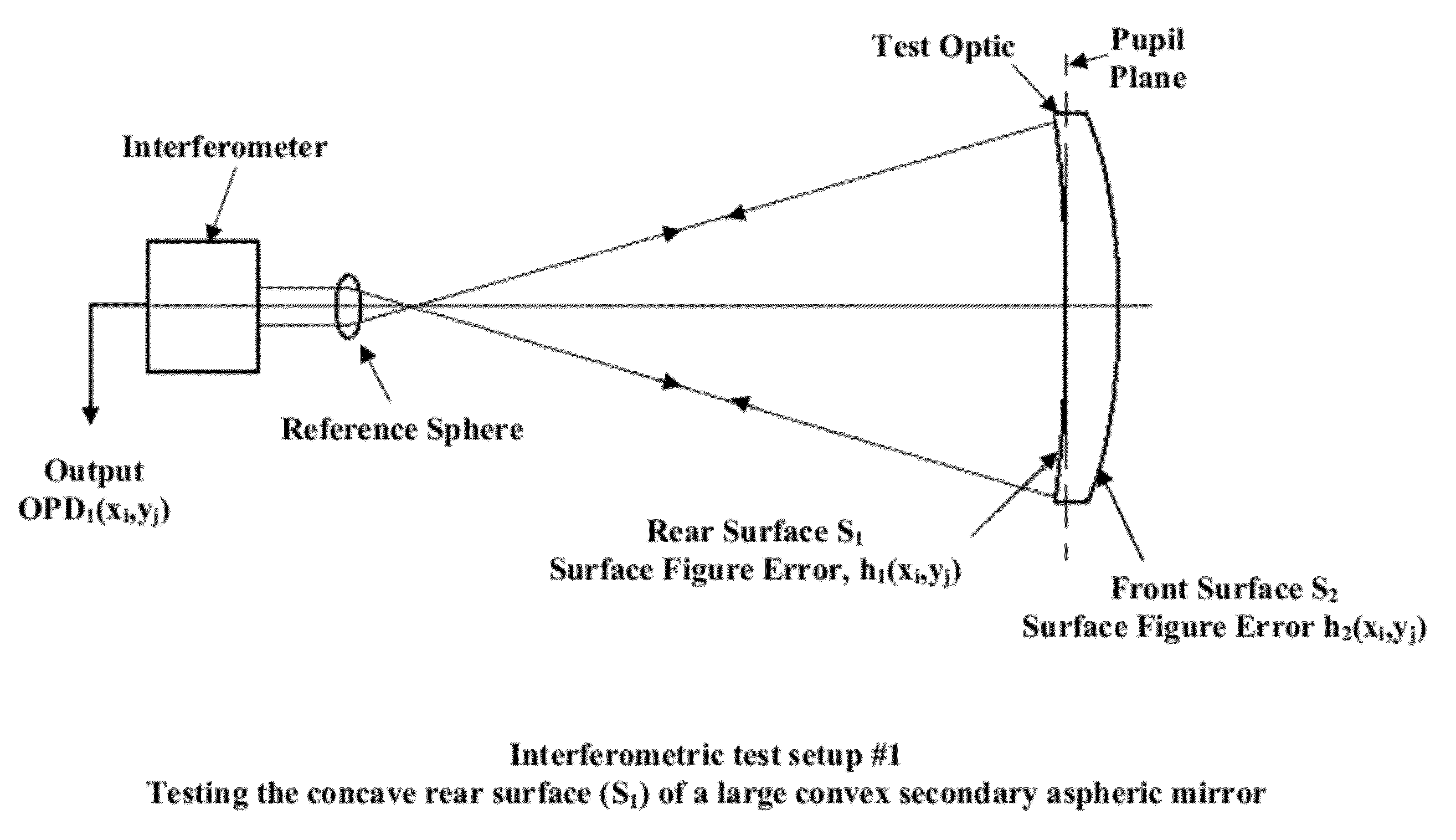
[0030]The test setup in FIG. 5 is inherently a null test if the rear surface S1 has a concave spherical shape. Thus, no null lens is needed for this particular test setup. Null lenses are shown in the other two test setups used in this example (FIGS. 6 and 7). Instead of using null lenses, one can also envisage use of Computer Generated Holograms (CGH) to null the aberrations. The diameters of the CGHs would need to be no larger than the null lens diameters; often their diameters would be smaller. FIG. 9 shows typical residual null test accuracy when simple null lenses are used with spherical or planar surfaces. Residual null test error could be entirely removed by use of multi-element null lenses (or mirrors), or aspheric null lenses, or by use of null CGHs.

[0031]The interferometric test setup #1 shown in FIG. 5 is used to test the concave rear surface S1 of a large convex secondary aspheric mirror, the test optic, for this example. The front...

case 2

Case 2: Using Test Setups #1, #2, and #4 (FIG. 8).

[0041]Test setups #1 and #2 are discussed above. In interferometric null test #4 in FIG. 8 the front surface S2 of the test optic is facing the interferometer. A coherent beam from the interferometer passes through the null lens, fills the test optic aperture, passes through the test optic, is reflected back through the test optic by the spherical return mirror, and back into the interferometer generating the optical path difference array OPD4(xi,yj). This OPD array includes errors introduced by S1 and S2 and any inhomogeneity in the substrate material

Mathematical Analysis for Case 2:

[0042]OPD4(xi,yj) is given by the following equation:

OPD4(xi,yj)=−2·(n−1)·h2(xi,yj)+2·(n−1)·h1(xi,yj)+2·OPDI(xi,yj).  (7)

When interferometric tests #1, #2, and #4 are used as the three independent tests, Equations 1, 2, and 7 have the following solutions for h1(xi, yj), h2(xi,yj) and OPDI(xi,yj):

[0043]⁢h1⁡(xi,yj)=OPD1⁡(xi,yj)2,(8)⁢h2⁡(xi,yj)=OPD4⁡(xi,yj)...

case 3

Case 3: Using Test Setups #1 and #2 only where OPDI(xi,yj) is Assumed to be Zero)

Mathematical Analysis for Case 3

[0044]For this degenerate case, OPDI(xi,yj)=0, Equations 1 and 2 (and Equations 8 and 9) have the following solutions for h1(xi,yj) and h2(xi,yj):

[0045]h1⁡(xi,yj)=OPD1⁡(xi,yj)2(11)h2⁡(xi,yj)=(n-1)·OPD1⁡(xi,yj)-OPD2⁡(xi,yj)2·n(12)

[0046]As previously, data obtained from Equation 11 for h1(xi,yj) can be used to improve the surface figure accuracy of the rear surface of the test optic. Similarly, data obtained from Equation 12 for h2(xi,yj) can be used to improve the surface figure accuracy of the front surface of the test optic.

[0047]Again, while it might only be necessary to correct rear surface figure error h1(xi,yj) to perhaps 1-λ (HeNe), the front surface figure error h2(xi,yj) generally would have to be corrected to higher accuracy, typically to λ / 10 (HeNe).


PUM


Abstract

A method of testing figure quality of a convex mirror in which an optical quality substrate material is used. Three separate interferometric null tests are carried out to produce three independent sets of optical path difference (OPD) data. Null lenses, or nulling computer generated holograms (CGHs), are designed and used as needed in each test setup so that spherical aberration is corrected. From the three sets of OPD data, surface figure errors on the rear and front surfaces of the test optic are calculated as well as the OPD error introduced by refractive index inhomogeneity in the substrate material. The rear surface is then corrected, generally using a computer-controlled polishing machine, to reduce rear surface errors to a manageably small level. The front convex surface of the test optic is then corrected to reduce surface figure error to within some specified amount.

Description

BACKGROUND OF THE INVENTION[0001]The invention relates generally to an interferometric method for testing large convex (spherical or aspheric) mirror surfaces. These convex mirrors are typically used as the secondary mirrors of Cassegrain and related telescope types such as Ritchey-Chretien. The invention is a further improvement on the methods described in U.S. patent application Ser. No. 12 / 343,683 filed Dec. 24, 2008 and Ser. No. 12 / 467,278 filed May 17, 2009, wherein the mirror is initially treated as a lens to obtain a precise surface figure for the convex surface prior to applying a reflective coating. These applications are hereby incorporated by reference. While this invention is primarily concerned with testing large (or small) convex mirror surfaces, the same type of test can be applied to testing lenses, in particular lenses with at least one convex surface (spherical or aspheric).[0002]Large convex mirrors are typically used as secondary mirrors in large reflecting teles...

Claims


Application Information

Patent Timeline
Patent Type & Authority Patents(United States)
IPC IPC(8): G01B11/02
CPCG01M11/005
Inventor MCKECHNIE, THOMAS STEWART
Owner MCKECHNIE THOMAS STEWART
Why Eureka
Try Eureka