At-command analyzing method

a technology of at-command and analyzing method, which is applied in the direction of synchronising signal speed/phase control, transmission monitoring, baseband system details, etc., can solve the problems of large circuit size, inability to perform functions in the above-described method, and complicated circuit arrangement, so as to reduce the size and complexity of the peripheral circuit

Inactive Publication Date: 2008-01-22
RICOH KK
View PDF12 Cites 3 Cited by
  • Summary
  • Abstract
  • Description
  • Claims
  • Application Information

AI Technical Summary

Benefits of technology

[0027]The present invention has been devised in consideration of the above-described problems. An object of the present invention is to reduce the size and complexity of the peripheral circuit when the rate of the AT command is analyzed. Another object of the present invention is to provide an error detecting function for immediately detecting the error that the first character is neither ‘A’ nor ‘a’.

Problems solved by technology

Thereby, the circuit arrangement is complicated, and the size of the circuit is large.
However, these functions cannot be performed in the above-described method in the prior art.
However, in a case of high-rate data, this determination may be delayed due to use of software, and, thereby, there is a possibility that the subsequent character cannot be received properly.
Further, in asynchronous communication, when an abnormal frame character which does not have the stop bit is generated, because the stop bit is not checked in this prior art, it is not possible to recognize this character to be an erroneous character.

Method used


Image

  • At-command analyzing method
  • At-command analyzing method
  • At-command analyzing method

Examples


Embodiment Construction

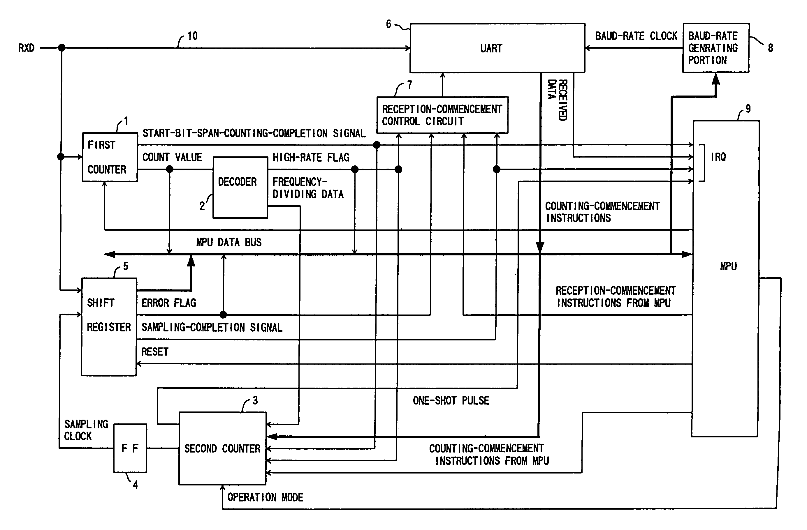
[0051]An embodiment of the present invention will now be described in accordance with drawings. FIG. 3 is a block diagram showing an AT-command analyzing device in the embodiment of the present invention.

[0052]In this embodiment, a first counter 1, a second counter 3 and a baud-rate generating portion 8 operate at a clock frequency of 3.6868 MHz.

[0053]The first counter 1 acting as a measuring portion is a counter which measures the span of the low period of the start bit of the first character of the AT command using received data transmitted through an RXD line 10 (serial line). The first counter 1 counts pulses of the clock for the low period starting from the time the level the received data decays, outputs the thus-obtained count value to an MPU data bus and a decoder 2, and outputs a counting-completion interrupt signal to an MPU 9. In a case of the highest baud rate of 230.4 kbps, the count value of the start bit of the first counter 1 is 10H. However, when considering the all...


PUM


Abstract

An UART receives asynchronous transmission serial data based on a baud-rate clock from a DTE. An MPU analyzes the data received by the UART. A baud-rate generating portion generates the baud-rate clock to be output to the UART in accordance with instructions from the MPU. A first counter measures the span of the start bit of the first character of an AT command transmitted from the DTE based on instructions from the MPU. A decoder receives a measurement result of the first counter, outputs frequency-dividing data for producing a clock for sampling the first character, and also outputs, when the rate of the start bit is more than a preset value, a flag indicating this matter. A second counter selects, in accordance with whether or not the flag is has been set, the frequency-dividing data from either the decoder or the MPU, and produces the sampling clock. A shift register receives data subsequent to the start bit of the first character based on the sampling clock from the second register, holds the received data, which data is then read by the MPU.

Description

CROSS REFERENCE TO RELATED APPLICATIONS[0001]The present application is a continuation application of U.S. patent application Ser. No. 09 / 479,889, filed on Jan. 10, 2000, now U.S. Pat No. 6,704,350 the disclosure of which is herewith incorporated by reference in its entirety.BACKGROUND OF THE INVENTION[0002]1. Field of the Invention[0003]The present invention relates to a device for analyzing an AT command which is used in a modem device for personal computer.[0004]2. Description of the Prior Art[0005]The AT command used in a modem device for a personal computer in the prior art automatically recognizes and responds to a communication rate and a communication parameter between a DTE (Data Terminal Equipment) and a DCE (Data Circuit Terminating Equipment).[0006]The AT command is such that the first two characters of the command are limited to ‘AT’ or ‘at’, and this is the reason why the AT command is called ‘AT’ command. What the AT command automatically recognizes and responds to is...

Claims


Application Information

Patent Timeline
Patent Type & Authority Patents(United States)
IPC IPC(8): H04B1/38H04L29/10H04L7/04H04L25/02
CPCH04L5/14H04L7/02H04L25/0262
Inventor RYU, TADANORIISHIZAKA, YASUHIROKINOSHITA, IZUMI
Owner RICOH KK
Why Eureka
Try Eureka