Power transmitting apparatus

a power transmission apparatus and power technology, applied in the direction of rotary clutches, fluid couplings, gearings, etc., can solve the problems of reducing the starting performance, affecting the efficiency of power transmission, so as to reduce complexity and size

Active Publication Date: 2012-08-21
FCC KK
View PDF6 Cites 2 Cited by
  • Summary
  • Abstract
  • Description
  • Claims
  • Application Information

AI Technical Summary

Benefits of technology

[0007]An aspect of at least one of the inventions disclosed herein includes the realization that the benefits of the torque converter type and lock-up clutch type transmissions can be combined in ways in which reduce the complexity and size of the above noted known combined-type apparatuses, while providing the benefits of the torque amplifying function of the torque converter types systems as well as the power transmitting efficiency of the clutch type systems.
[0008]More specifically, during steady operation of a vehicle having a torque converter type system, although it has a technical merit of improving the starting performance because of the torque amplifying function of the torque converter when movement is initially started, it can suffer from loss of some power transmitting efficiency because of slippage generated in the torque converter e.g. during steady run of a vehicle.
[0009]On the other hand, in the clutch type system, although it has a technical merit of improving the power transmitting efficiency because of not having any slippage which would be found in the torque converter e.g. during steady run of vehicle, it has a technical demerit of decreasing the starting performance since it does not have the torque amplifying function on start of a vehicle obtained by the torque converter. In order to prevent the decrease of the starting performance, the reduction ratio of such transmissions is usually increased.

Problems solved by technology

More specifically, during steady operation of a vehicle having a torque converter type system, although it has a technical merit of improving the starting performance because of the torque amplifying function of the torque converter when movement is initially started, it can suffer from loss of some power transmitting efficiency because of slippage generated in the torque converter e.g. during steady run of a vehicle.
On the other hand, in the clutch type system, although it has a technical merit of improving the power transmitting efficiency because of not having any slippage which would be found in the torque converter e.g. during steady run of vehicle, it has a technical demerit of decreasing the starting performance since it does not have the torque amplifying function on start of a vehicle obtained by the torque converter.
Further, the known system described in Japanese Laid-open Patent Publication No. 3193 / 2005, which is a combined torque converter and clutch type, is a relatively large and complicated structure in which the lock-up clutch is movable between the connected position and the non-connected position in the hydraulic atmosphere within the torque converter.
This increases both the manufacturing cost and the maintenance cost.

Method used


Image

  • Power transmitting apparatus
  • Power transmitting apparatus
  • Power transmitting apparatus

Examples


Embodiment Construction

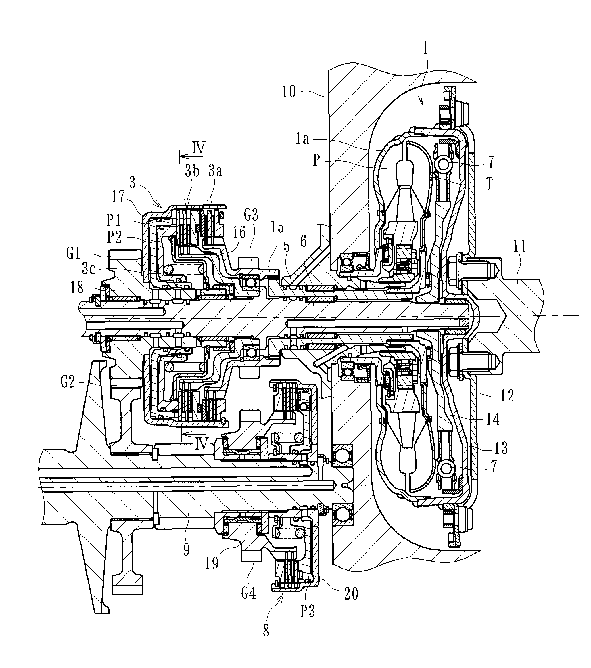
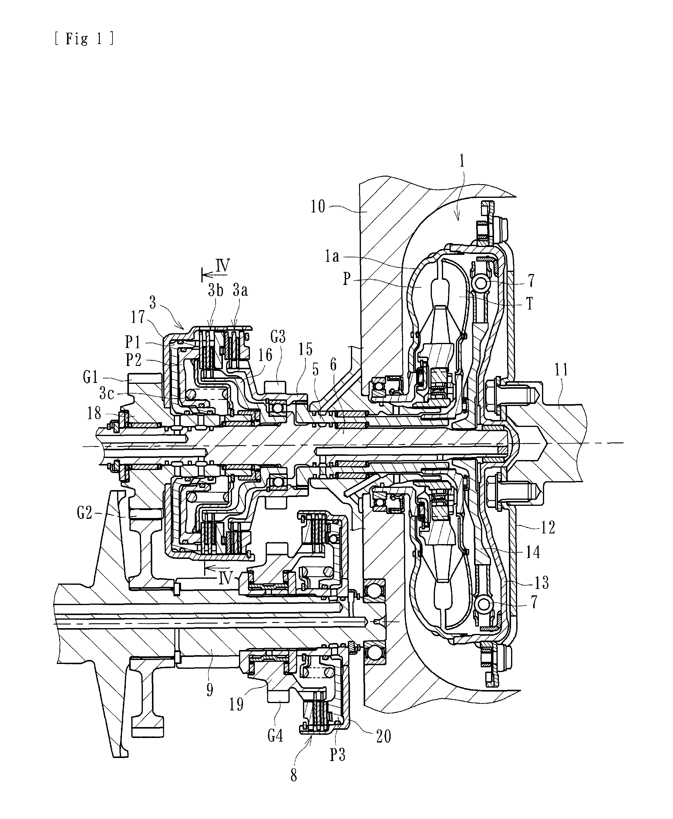
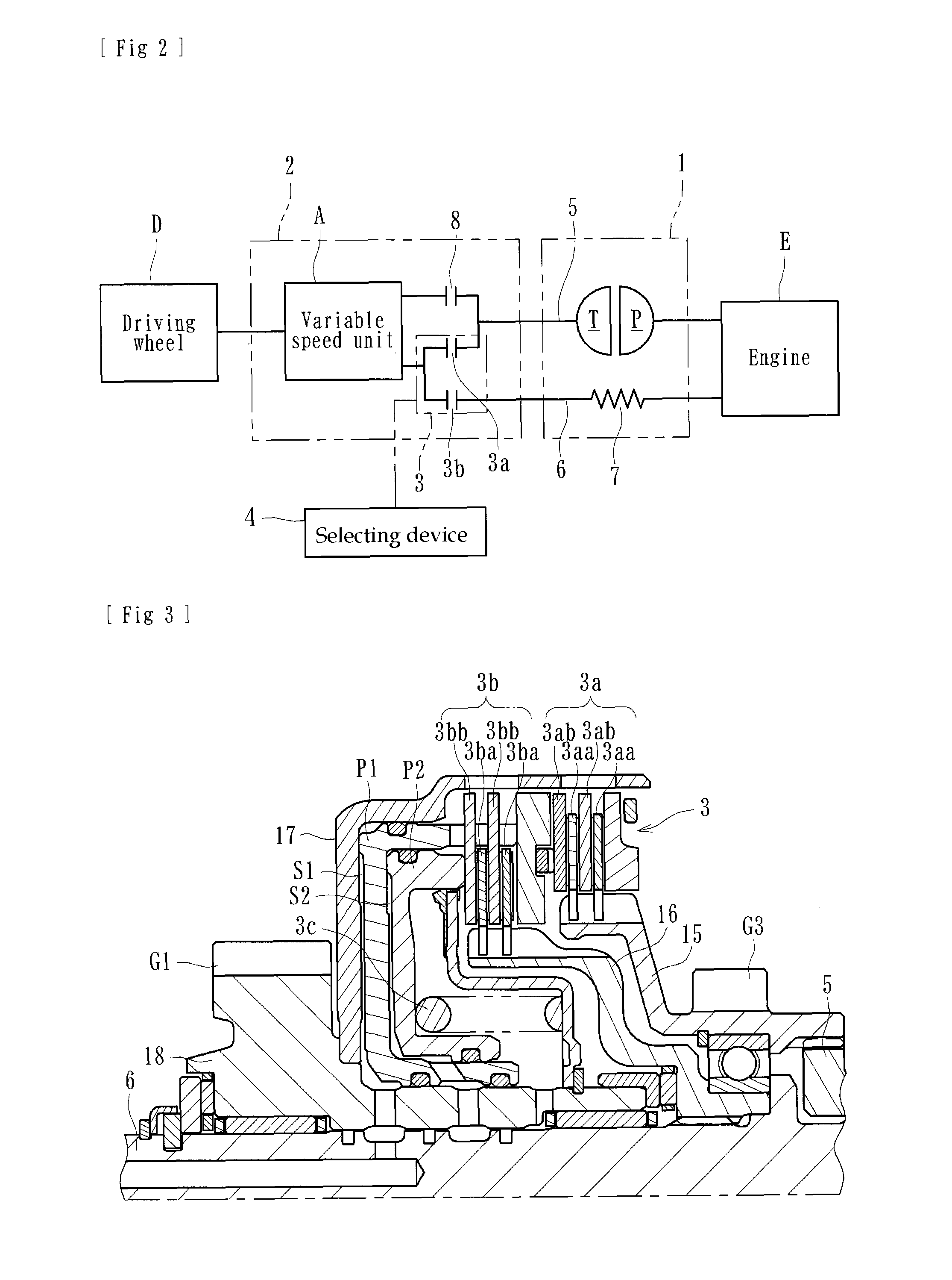
[0035]An embodiment of a power transmitting apparatus can be configured to transmit or cut-off the driving force from an engine (driving source) of an automobile (vehicle) to or from the wheels (driving wheels). Such an apparatus can include, with reference to FIGS. 1 and 2, a torque converter 1, a clutch mechanism 3, a selecting device 4, a first driving shaft 5, a second driving shaft 6, a damper mechanism 7, and a third clutch device 8. FIG. 1 is a longitudinal cross-sectional view showing a part of the power transmitting apparatus, and FIG. 2 is a schematic diagram showing the power transmitting apparatus of FIG. 1.

[0036]As shown in FIG. 2, the torque converter 1 and a transmission 2 can be arranged as a power transmitting system for transmitting power from the engine E as the driving source of a vehicle to wheels of the vehicle (driving wheels D). Here, the transmission 2 includes the clutch mechanism 3 (which can be referred to as a clutch means), a third clutch device 8 (whic...


PUM


Abstract

A power transmitting apparatus for transmitting power from a driving source of a vehicle to its wheels can be adapted to properly select transmitting or cutting-off of the driving force of the driving source to or from the wheels. The apparatus can comprise a torque converter having a torque amplifying function; a clutch mechanism including a first clutch device operable on advancement of the vehicle and adapted to transmit the driving force of the driving source to the wheels through a power transmitting system of the torque converter and a second clutch device adapted to transmit the driving force of the driving source to the wheels without the power transmitting system of the torque converter. A selecting device can be configured to operate the first clutch device and / or the second clutch device in accordance with operation modes of the vehicle, including starting.

Description

CROSS-REFERENCE TO RELATED APPLICATIONS[0001]This application is a continuation of PCT Application No. PCT / JP2009 / 003208 filed Jul. 9, 2009, which claims priority to Japanese Application No. 2008-253076, filed Sep. 30, 2008, the entire contents of each of which are hereby incorporated by reference.BACKGROUND OF THE INVENTIONS[0002]1. Field of the Inventions[0003]The present inventions relate to power transmitting apparatuses for transmitting power from a driving source of a vehicle to its wheels and which are configured to selectively transmit or cut-off the driving force, to or from the wheels.[0004]2. Description of the Related Art[0005]Two types of known power transmitting apparatuses for vehicles (e.g., “automatic transmissions”) provide starting power (power for initiating movement of the vehicle from a stop) in different ways. One type uses a torque converter (“tor-con type”) and another type uses a starting clutch (“starting clutch type”) to provide starting power used to sta...

Claims


Application Information

Patent Timeline
Patent Type & Authority Patents(United States)
IPC IPC(8): F16D25/10F16H45/00
CPCF16D25/0638F16D25/10F16H45/02F16H61/143F16H2045/002F16H2045/005F16H2045/0252F16D2021/0661F16D21/06
Inventor OHASHI, TATSUYUKIASATSUKE, SHOUJIOISHI, AKIOCHIBA, RYOUHEIISHIMURA, JUNISHIKAWA, KEIICHI
Owner FCC KK
Why Eureka
Try Eureka