Fluorescent Display Tube

a technology of fluorescent display tubes and supporting structures, which is applied in the direction of discharge tubes/lamp details, discharge tubes with screens, discharge tubes luminescnet screens, etc., can solve problems such as difficulty in handling, and achieve the effects of reducing filament current, reducing current flowing through filaments, and applying voltag

Inactive Publication Date: 2010-05-13
FUTABA CORPORATION
View PDF0 Cites 2 Cited by
  • Summary
  • Abstract
  • Description
  • Claims
  • Application Information

AI Technical Summary

Benefits of technology

[0024]As explained above, a fluorescent display tube according to the present invention includes filament cathodes provided in series and extended from the first supporting metal plate to the second supporting metal plate via the third supporting metal plate. Thus, the applied voltage can be more than double while reducing the current flowing through the filaments more than half compared to conventional fluorescent display tubes. Therefore, a filament power source of 3 to 8V can be applied to the fluorescent display tube with short filament length. Thus for the fluorescent display tube with one filament cathode, the filament cathode can be lighted with current of about 25 mA. As a result, the filament current can be reduced enabling easier control of turning on and off of the filaments of the fluorescent display tube. Furthermore, since lead wires for inputting electrical signal for the filament and lead wires for inputting anode signal and grid signal can be provided to different blocks, easier layout of a circuit substrate is achieved.

Problems solved by technology

Therefore, while the voltage employed in a filament power source for a typical fluorescent display tube is about 3V, the voltage applied to the fluorescent display tube with short filament length is for example only about 2V, causing it to be difficult to handle.

Method used


Image

  • Fluorescent Display Tube
  • Fluorescent Display Tube
  • Fluorescent Display Tube

Examples


first embodiment

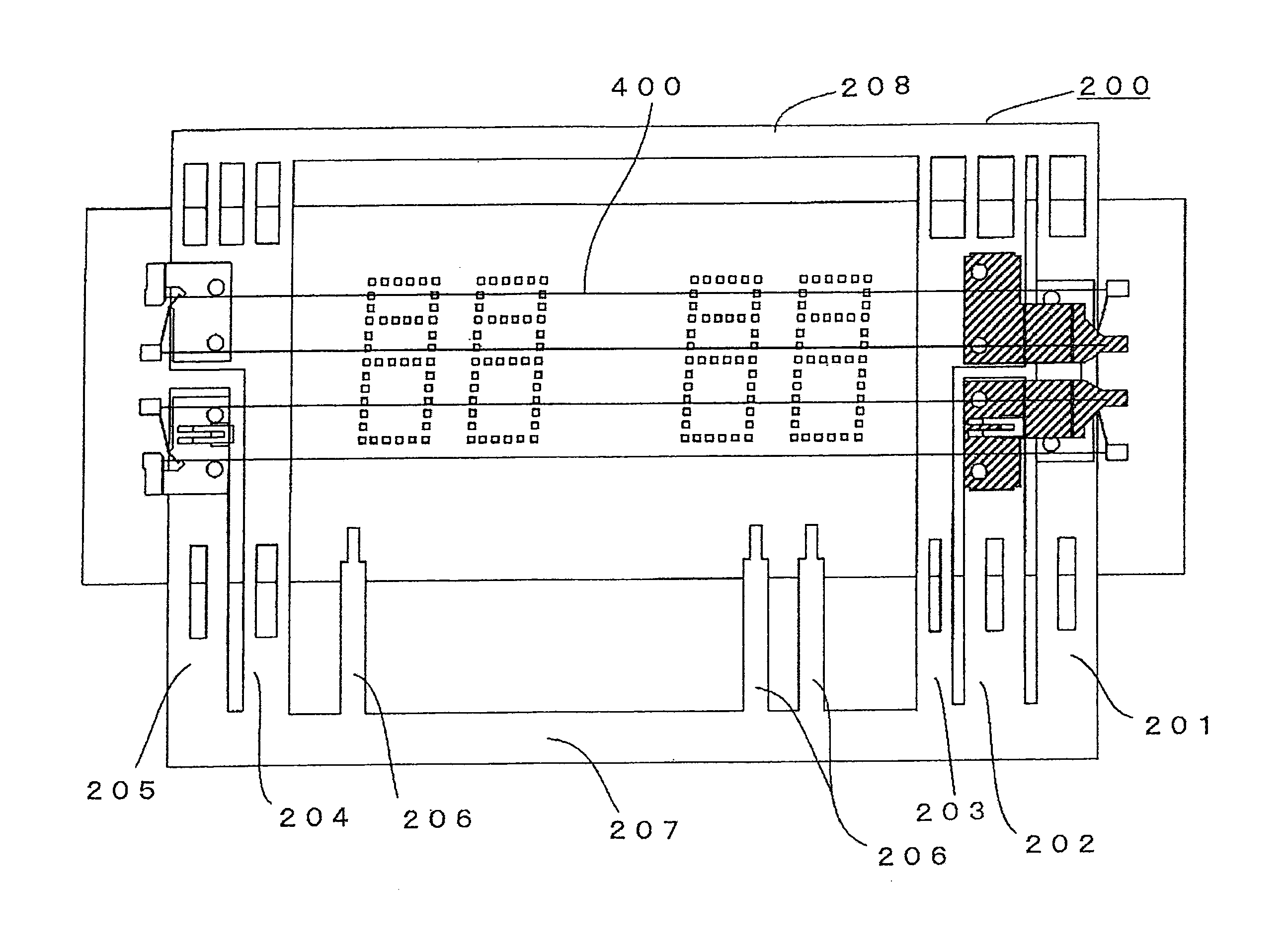
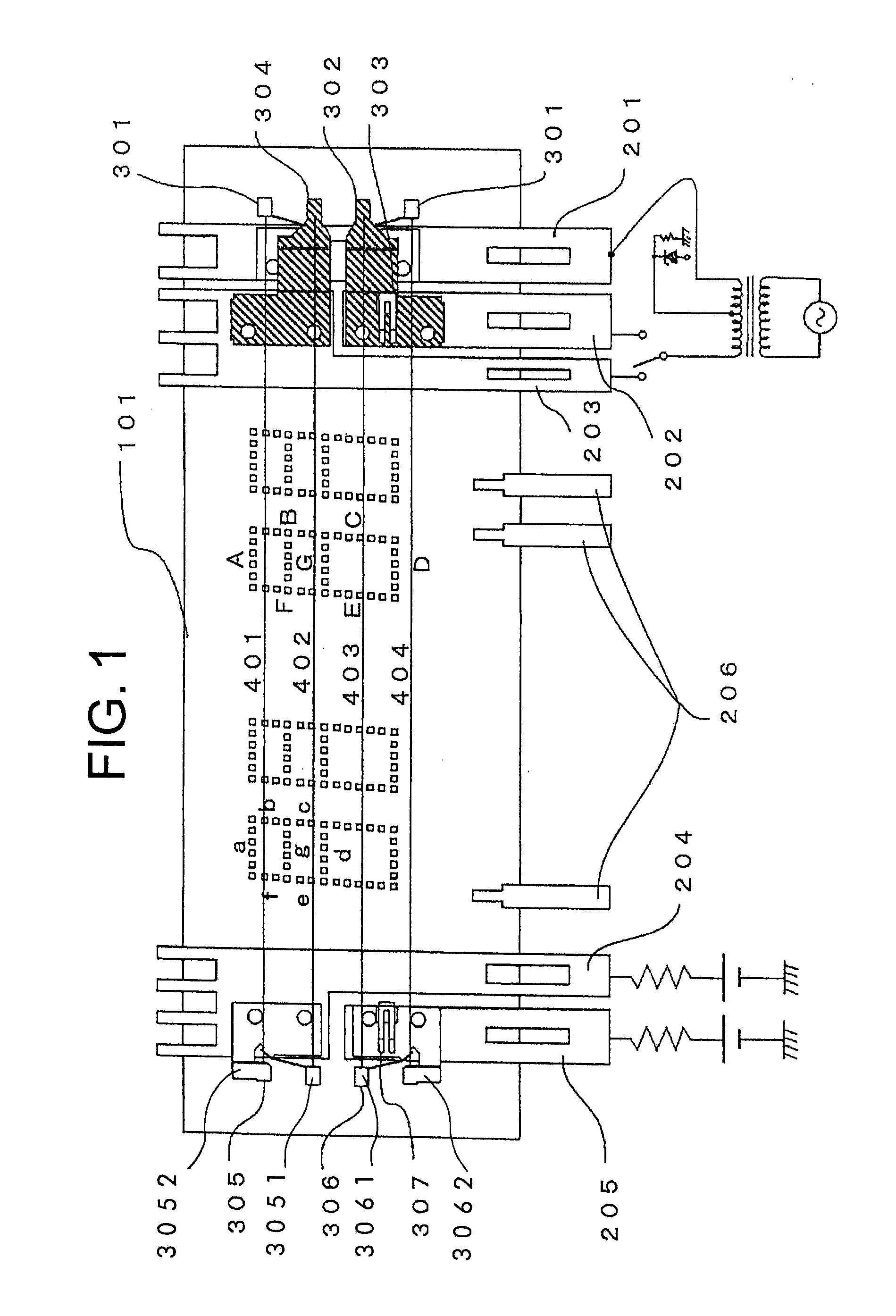
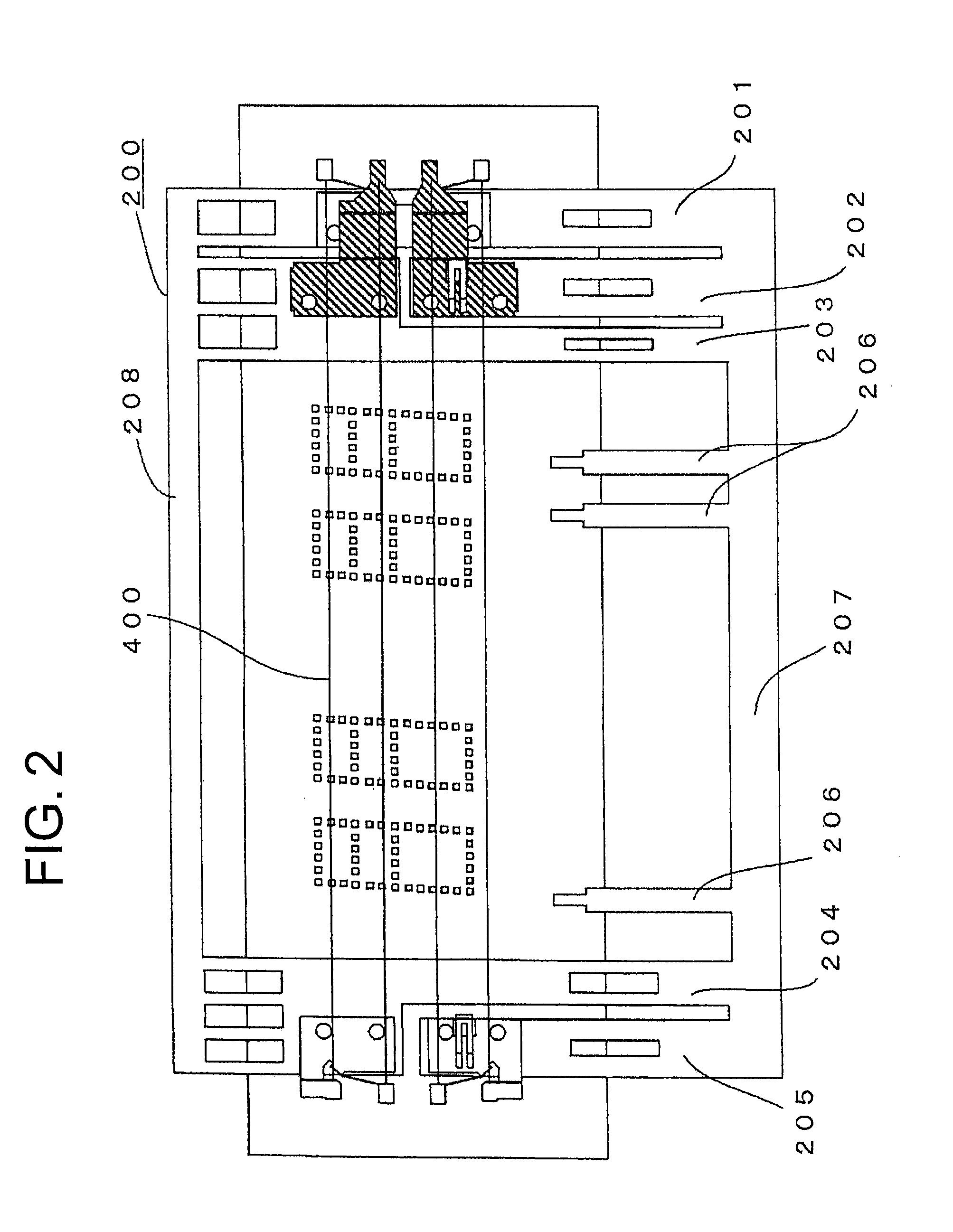
[0034]A first embodiment of the present invention is explained with reference to the FIGS. 1 to 4. FIG. 1 shows a schematic view of the first embodiment of a fluorescent display tube according to the present invention, and FIG. 2 shows a frame according to the first embodiment. FIGS. 3 and 4 provide supplementary explanation of FIG. 1. A frame 200 of the first embodiment includes: a first supporting metal plate 201; second supporting metal plates 202, 203 arranged adjacent to the first supporting metal plate 201; and third supporting metal plates 204, 205 provided at a distance from the second supporting metal plates 202, 203. Lead wires 206 inputting an electrical signal to an anode plate and grids are provided between the second and third supporting metal plates and are connected to a connecting portion 207 shown in FIG. 2. The connecting portion 207 is connected to an opposite connecting portion 208 via the second and third supporting metal plates to form the frame 200.

[0035]The ...

second embodiment

[0047]A second embodiment of the present invention is explained with reference to the FIG. 5. FIG. 5 shows a fluorescent display tube according to the second embodiment in which two sets of phosphor segments of the first embodiment are provided in two rows as shown and in which the number of provided filament cathodes is doubled. In this embodiment, the filament cathodes of the first embodiment (401, 402 and 403, 404) are provided in parallel as shown. This fluorescent display tube of the second embodiment enables application of the voltage between the first supporting metal plate 211 and the second supporting metal plates 212, 213 via the third supporting metal plates 214, 215. In this case, the filament cathodes 405, 406 and 407, 408 are electrically connected in parallel, so the fluorescent display tube can be driven by the voltage applied from the first supporting metal plate 211 and the second supporting metal plates 213 via the third supporting metal plate 214. Consequently, t...

third embodiment

[0049]A third embodiment of the present invention is explained with reference to the FIG. 6. FIG. 6 shows a fluorescent display tube according to the third embodiment in which three pairs (413 and 414, 415 and 416, 417 and 418) of filament cathodes of the first embodiment are provided in three rows as shown. In the fluorescent display tube according to the third embodiment, the voltage is applied between the first supporting metal plate 221 (starting zero point) and the second supporting metal plates 222, 223 and 224 (end point) via the third supporting metal plates 225, 226 and 227. Thus, the phosphor segments emit light, separately for each block, with practically one filament cathode.

[0050]For example, for the fluorescent display tube according to the third embodiment shown in FIG. 6, if the voltage is applied between the first supporting metal plate 221 and the third supporting metal plate 225, only the filament cathode 413 lights-up. If the voltage is applied between the second...


PUM


Abstract

A fluorescent display tube, which has short-length filaments, can be driven by applied voltage of 3-8V to be used for a general fluorescent display tube. The fluorescent display tube can emit sufficient thermal electrons even if the number of filament cathodes is decreased to reduce power consumption of the filaments. The filament cathode is arranged between a first and third supporting plates by one end thereof fixed to the first supporting plate and the other end thereof fixed to the third supporting plate, and the filament cathode having an equal length with the filament cathode extended between the first and third supporting plates is arranged between the second and third supporting plates.

Description

CROSS-REFERENCE TO RELATED APPLICATIONS[0001]This application claims priority to Japanese Patent Application Number 2008-287715 filed on Nov. 10, 2008, the contents of which are fully incorporated herein by reference.STATEMENT REGARDING FEDERALLY SPONSORED RESEARCH[0002]Not Applicable.BACKGROUND[0003]1. Field of the Invention[0004]The present invention relates to a filament supporting structure of a fluorescent display tube having an anode plate with phosphor segments and filament cathodes inside an airtight container.[0005]2. Description of Related Art[0006]A reduction in power consumption of a fluorescent display tube has been demanded. To that end, filament cathodes are divided into blocks and are driven separately for each block so that current is not carried to the filament cathodes corresponding to a non-displaying region.[0007]A fluorescent display tube, shown in FIG. 7, is a light emitting device including an airtight container which is provided therein with an anode substra...

Claims


Application Information

Patent Timeline
Patent Type & Authority Applications(United States)
IPC IPC(8): H01J1/62
CPCH01J31/15H01J31/12
Inventor IIZAWA, TAKEHIRONARUSHIMA, SHINICHITOKURA, KATSUSHISHIMIZU, YUKIHIKOHEYNEN, KLAUS
Owner FUTABA CORPORATION
Why Eureka
Try Eureka