
Magnetic resonance device comprising an asymmetrical cylindrical gradient coil and at least one asymmetrical shim-coil

Inactive Publication Date: 2010-05-13
SIEMENS HEALTHCARE GMBH
View PDF9 Cites 6 Cited by
  • Summary
  • Abstract
  • Description
  • Claims
  • Application Information

AI Technical Summary

Benefits of technology

[0008]Departing from known gradient coils, an asymmetry is provided both on the part of the gradient coils and also at least one part of the shim coils, primarily those that can couple with an asymmetrical gradient coil. According to the invention, the symmetry of the shim coils relative to the z-direction is thus also destroyed. The direction of the coil conductor is not arbitrarily asymmetrical; rather, the coil conductor is directed such that the coupling to the shim coils that would have been possible due to the asymmetry of the x- and y-gradient coils is minimized. The design of the shim coils is thus oriented on the design of the asymmetrical gradient coils such that a minimized coupling inductance results, so that possible voltages induced due to a residual coupling are largely negligible but in any case represent no load for the shim amplifier. Because the geometry of the asymmetrical x- and y-gradient coils is known and because the geometry of the available space within which the shim coil is directed is known, the optimal coil conductor direction can be determined using the gradient coil geometry and structural space geometry. The asymmetrical design also offers more freedom in the selection of the conductor positions, such that it is possible to minimize the coupling inductance between gradient coil and shim coil without having to accept curtailments in the precision of the field curve.

Problems solved by technology

Other couplings are not possible due to the peripheral geometry as provided before.

Method used


Image

  • Magnetic resonance device comprising an asymmetrical cylindrical gradient coil and at least one asymmetrical shim-coil
  • Magnetic resonance device comprising an asymmetrical cylindrical gradient coil and at least one asymmetrical shim-coil
  • Magnetic resonance device comprising an asymmetrical cylindrical gradient coil and at least one asymmetrical shim-coil

Examples


Embodiment Construction

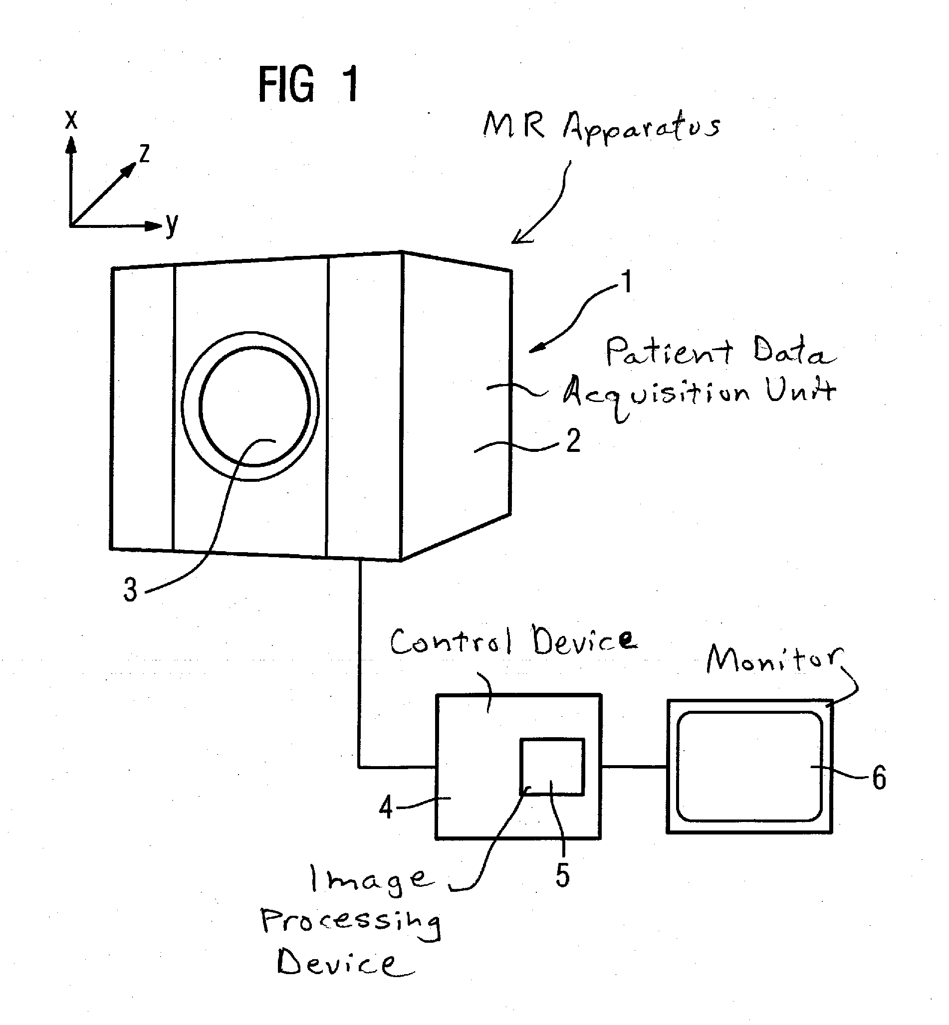
[0019]FIG. 1 shows the basic components of an inventive magnetic resonance apparatus 1 that includes a patient data acquisition unit 2, having a gradient coil 3 with which (controlled by a control device 4) a gradient field is generated that serves in a known manner for the spatial resolution of the acquired measurement signals. The control device 4 includes an image processing device 5 that, using the acquired measurement signals, generates magnetic resonance images that can be output to a monitor 6. The fundamental design and the functions and mode of operation of a magnetic resonance apparatus are sufficiently known to those skilled in the art so as to need no further explanation.

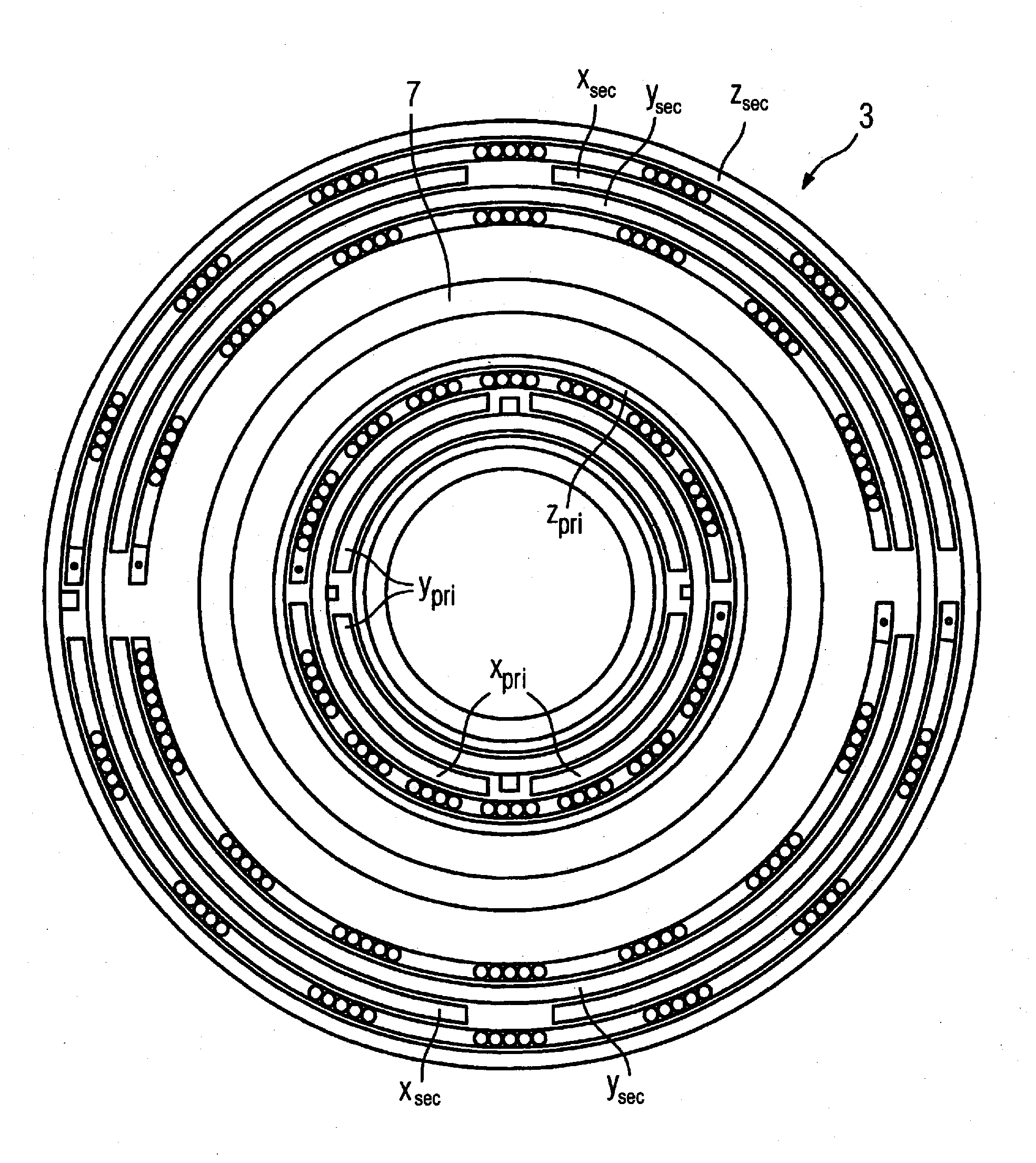
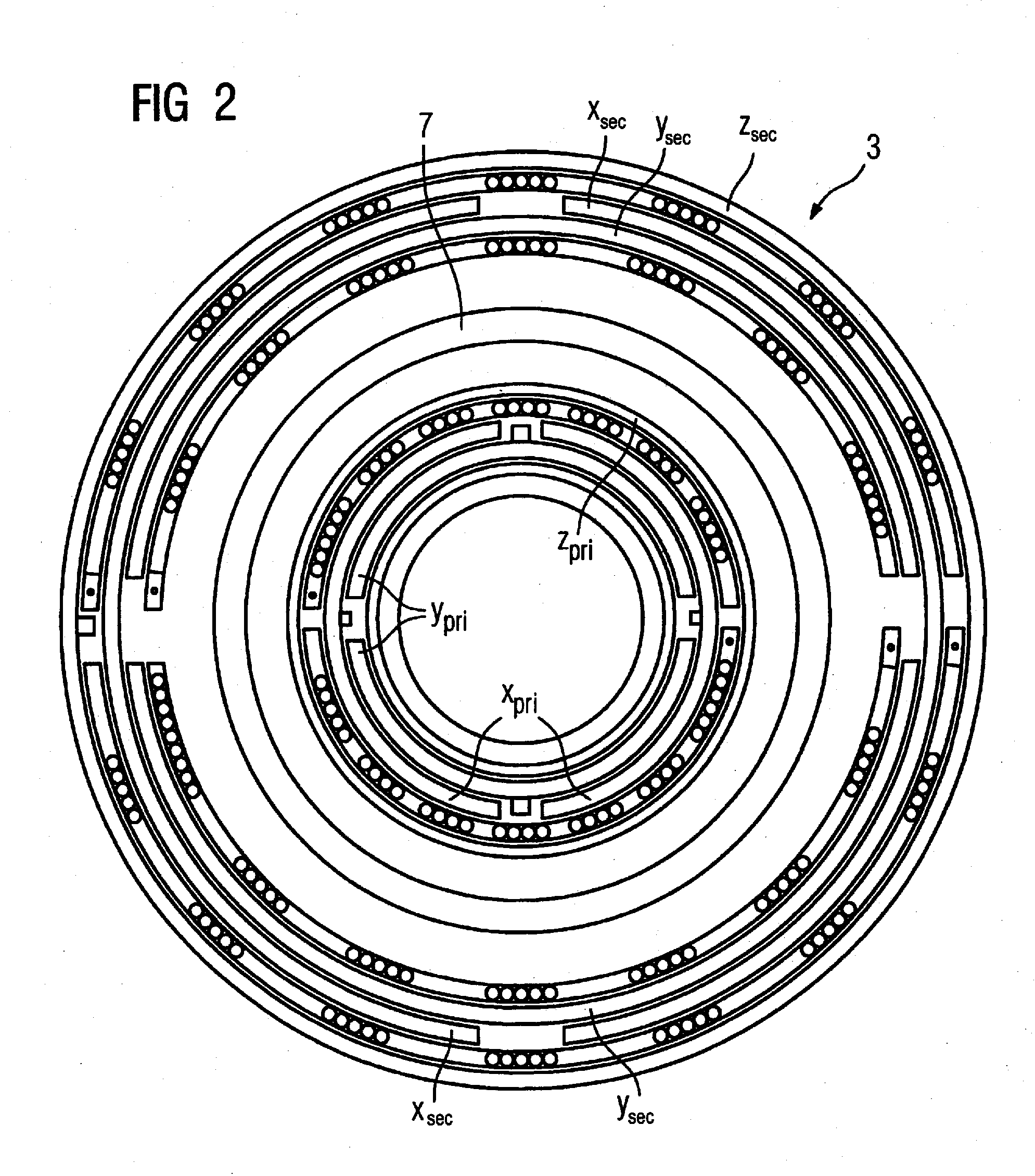
[0020]FIG. 2 shows a section view of a gradient coil 3 that is cylindrical and tube-shaped. This has three individual coils, namely the x-coil, the y-coil and the z-coil situated furthest outwardly as viewed radially. The x-coil and the z-coil are each formed by two coil halves. The coil conductors are a...


PUM


Abstract

A magnetic resonance apparatus has a cylindrical gradient coil with an x-gradient coil and a y-gradient coil that are asymmetrical relative to the z-direction of a coordinate system, the z-direction extending along a longitudinal direction of a patient receptacle. Shim coils are provided that generate magnetic fields to homogenize the basic magnetic field, produced by a cylindrical basic field magnet, in an examination volume in the patient receptacle. At least some of the shim coils are asymmetrical relative to the z-direction to minimize coupling induction between the asymmetrical x-gradient coil and y-gradient coil and the asymmetrical shim coils.

Description

BACKGROUND OF THE INVENTION[0001]1. Field of the Invention[0002]The invention concerns an magnetic resonance apparatus of the type having a cylindrical gradient coil with x- and y-coils directed asymmetrically relative to a z-direction (running along a patient receptacle) of a shim coils for generation of magnetic fields serving for the homogenization coordinate system, as well as a number of a basic magnetic field generated by means of a cylindrical basic field magnet.[0003]2. Description of the Prior Art[0004]A magnetic resonance apparatus serves for the high-resolution acquisition of images of an examination subject using magnetic fields. Various magnetic fields are generated for this purpose. A static basic magnetic field is generated using a (normally cylindrical) basic field magnet, whereby the field strength normally being between 0.2 and 10 T. Furthermore, a radio-frequency excitation field (B1 field) for excitation of the nuclear spins is generated using a radio-frequency c...

Claims


Application Information

Patent Timeline
IPC IPC(8): G01R33/44
CPCG01R33/3875G01R33/385
Inventor RIEGLER, JORGENDT, AXEL VOM
Owner SIEMENS HEALTHCARE GMBH
Learn More