LED outage detection circuit

a detection circuit and led technology, applied in the direction of instruments, electroluminescent light sources, electric lighting sources, etc., can solve the problems of not being suitable for use with leds, not being able to generate signals, and using complex and expensive circuitry in known prior art systems, etc., to achieve simple and cost-effective effects

Active Publication Date: 2010-05-13
SIGNIFY HLDG BV
View PDF12 Cites 40 Cited by
  • Summary
  • Abstract
  • Description
  • Claims
  • Application Information

AI Technical Summary

Benefits of technology

[0005]It is an object of the present invention to provide a simple, cost-effective...

Problems solved by technology

However, if a lamp breaks during use, no signal is generated.
Further, known prior art systems use complex and expensive circuitry in order to detect a defective lamp.
Moreover, a known prior art warning system is not suitab...

Method used


Image

  • LED outage detection circuit
  • LED outage detection circuit
  • LED outage detection circuit

Examples


Embodiment Construction

[0018]In the drawings, same reference numerals refer to same elements.

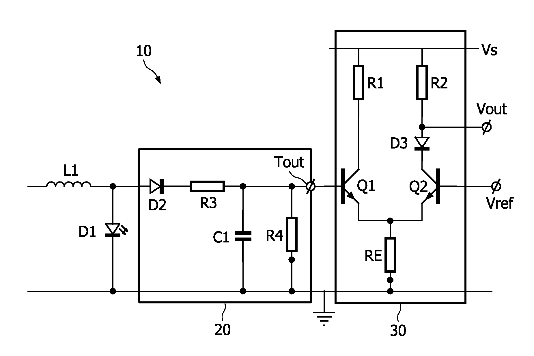
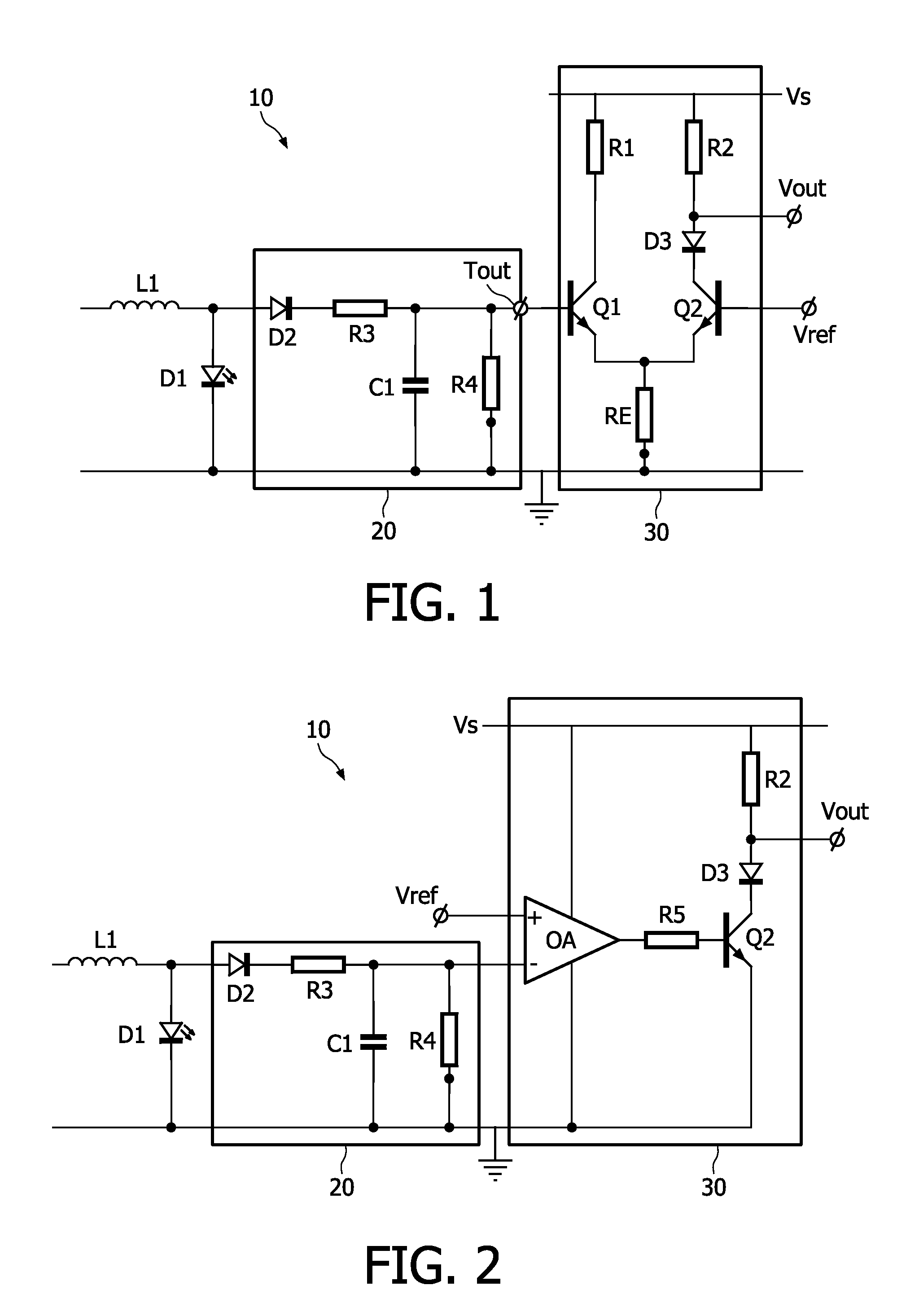
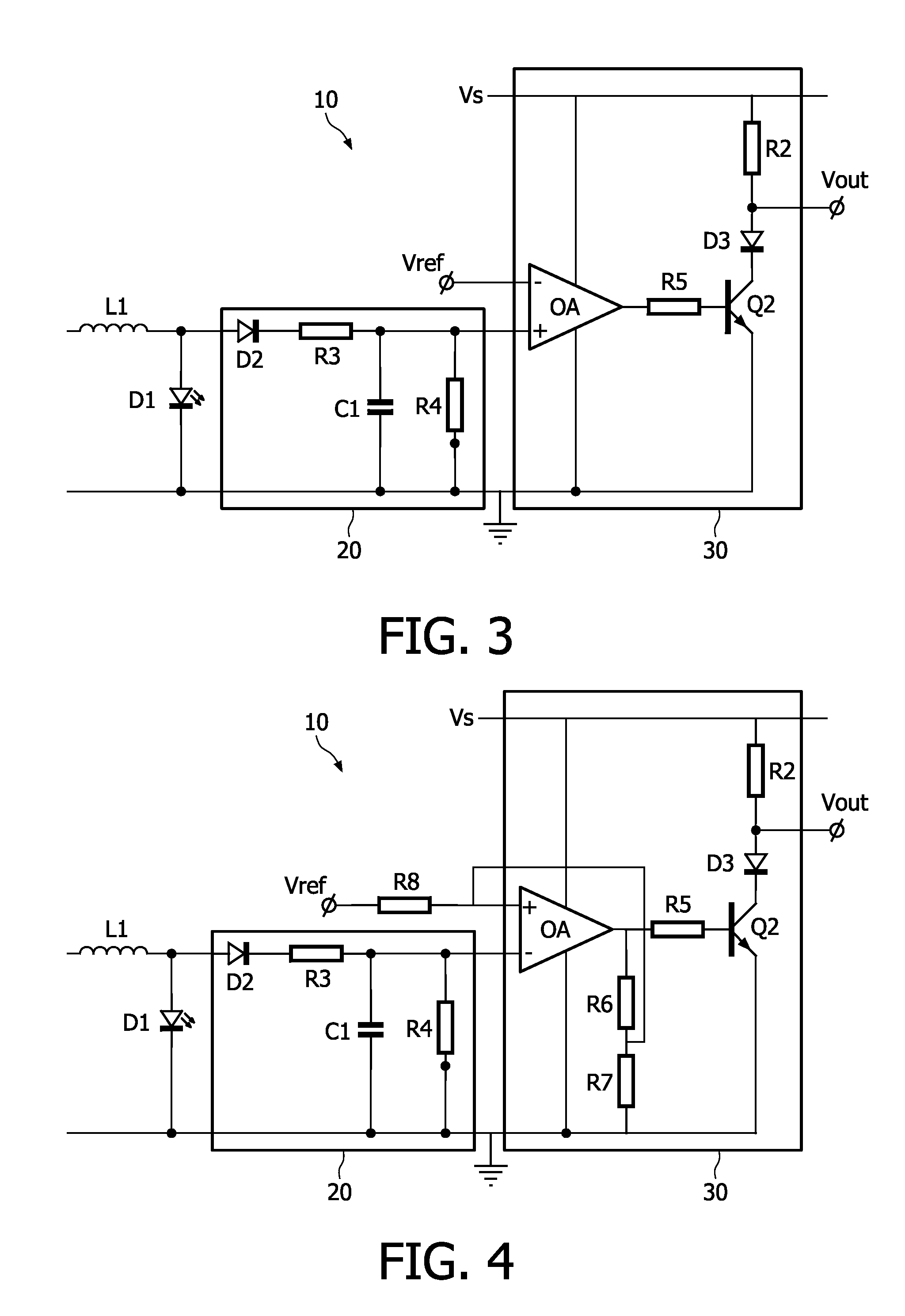
[0019]FIG. 1 shows a first embodiment of an outage detection circuit 10 in accordance with the present invention. The outage detection circuit 10 comprises a top voltage detector 20 and a differential amplifier 30. The top voltage detector 20 is coupled to a LED D1. The LED D1 is to be monitored and an outage detection signal should indicate the status of the LED D1. An inductor L1 is coupled across the LED D1. The inductor L1 is a part of a DC-DC converter for providing power to the LED D1. The inductor L1 is not essential. Any other DC-DC converter topology may be applied as well.

[0020]The top voltage detector 20 comprises a charge diode D2, a current limiting resistor R3, a capacitor C1 and a discharge resistor R4. The charge diode D2, the current limiting resistor R3 and the capacitor C1 are connected in series across the LED D1. The discharge resistor R4 is connected in parallel to the capacitor C1. The curre...


PUM


Abstract

In order to detect a defective light source, such as a LED coupled to a DC-DC converter circuit for receiving a power signal, an outage detection circuit comprises a top voltage detector coupled to the LED for detecting a voltage across the LED. The top voltage detector has an top voltage terminal for supplying a top voltage signal. The detection circuit further comprises a differential amplifier coupled to the top voltage terminal for receiving the top voltage signal as a first input signal and coupled to a reference voltage terminal. The reference voltage terminal is configured to supply a reference voltage as a second input signal. The differential amplifier comprises an output terminal for supplying an outage detection signal.

Description

FIELD OF THE INVENTION[0001]The present invention relates to an LED outage detection circuit for detecting a defective LED and outputting a corresponding detection signal.BACKGROUND OF THE INVENTION[0002]In e.g. automotive applications, it is desirable to have a warning system to indicate to a driver that a lamp of a lighting system, in particular tail lighting and / or break lighting, is defective. In response to the warning, the driver may replace the defective lamp.[0003]A known prior art system requires a test mode or the like. For example, each time the lighting system is switched on or when a car is started, the lighting system is checked. However, if a lamp breaks during use, no signal is generated. Further, known prior art systems use complex and expensive circuitry in order to detect a defective lamp.[0004]Moreover, a known prior art warning system is not suitable to be used with an LED. In particular, when an LED is dimmed, for example driven by a DC-DC converter circuit emp...

Claims


Application Information

Patent Timeline
IPC IPC(8): G01R31/00H05B44/00
CPCH05B33/0887H05B33/0893H05B45/58H05B45/50
Inventor SNELTEN, JEROEN
Owner SIGNIFY HLDG BV
Why Eureka
Try Eureka