Varistor

a technology of varistor and core, applied in the field of varistor, can solve the problems of affecting the operation of electronic devices and generating heat during operations, and achieve the effects of reducing heat generation, reducing heat generation, and reducing heat generation

Inactive Publication Date: 2010-05-13
TDK CORPARATION
View PDF5 Cites 10 Cited by
  • Summary
  • Abstract
  • Description
  • Claims
  • Application Information

AI Technical Summary

Benefits of technology

[0017]Preferably, the metal oxide constituting the varistor part and the metal oxide constituting the composite part are made of the same material. This can inhibit cracks from entering between the varistor part and composite part during firing and the like.
[0018]Preferably, the metal oxide and metal are ZnO and Ag, respectively. Since Ag disperses into grain boundaries of ZnO which is the main ingredient of the varistor matrix, the joint strength between the varistor part and composite part can be enhanced.
[0019]As in the foregoing, the varistor in accordance with the present invention can yield a favorable heat-dissipating property.

Problems solved by technology

However, many of electronic devices generate heat during their operations.
At high temperatures, the electronic devices themselves deteriorate their characteristics, thereby affecting their operations.

Method used


Image

  • Varistor
  • Varistor
  • Varistor

Examples


first embodiment

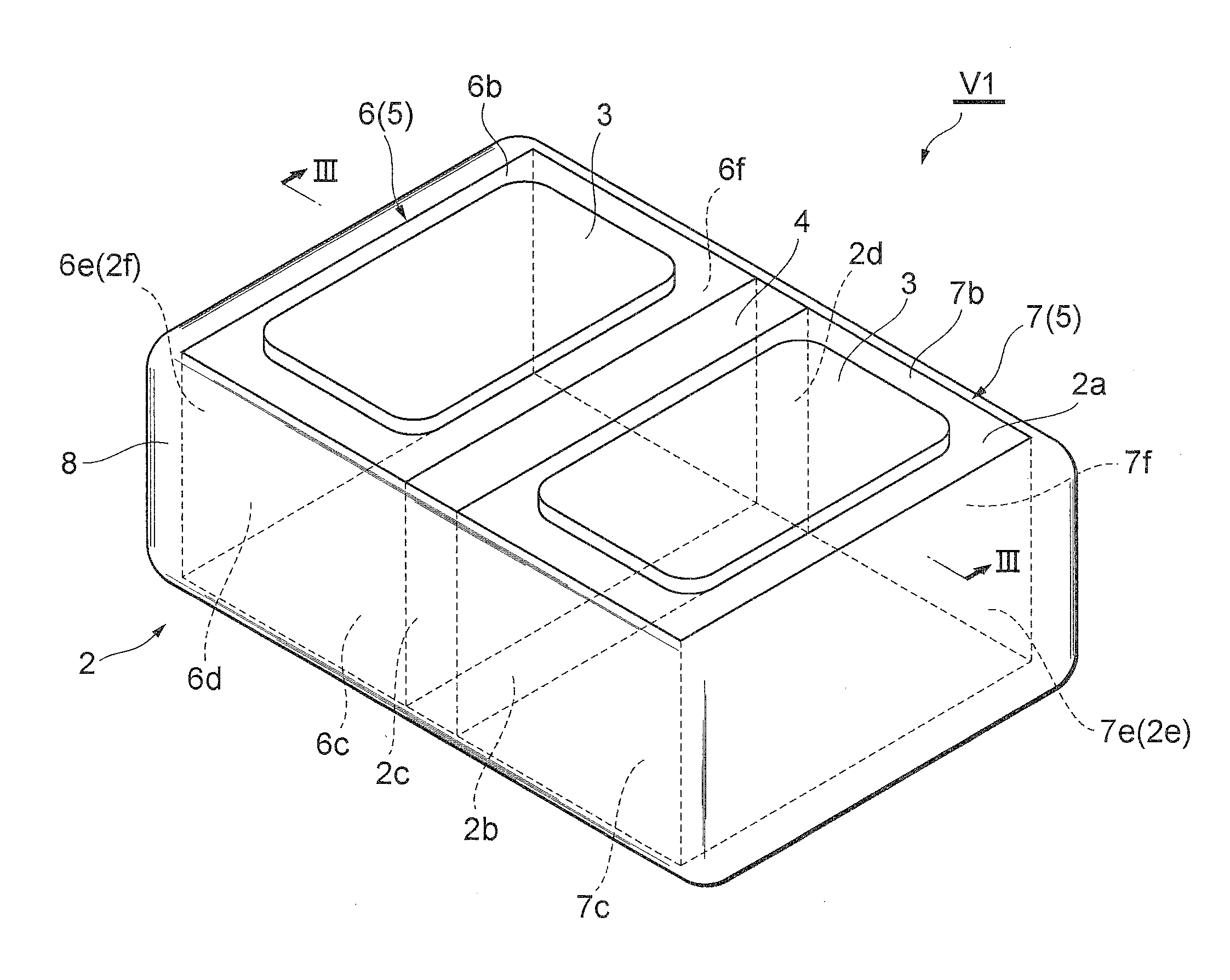
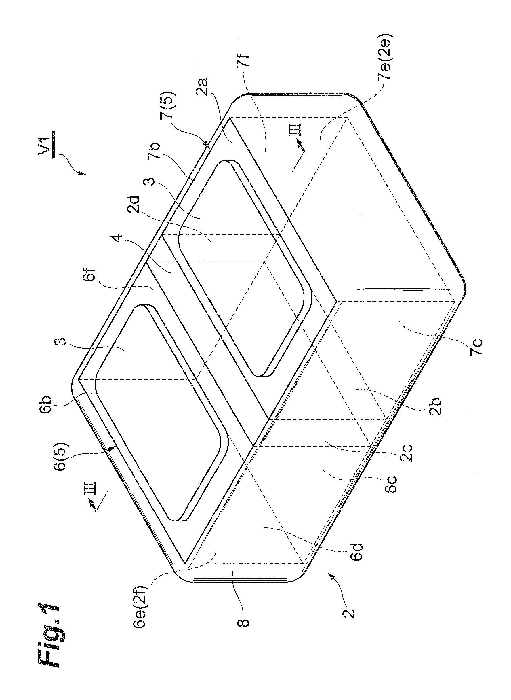
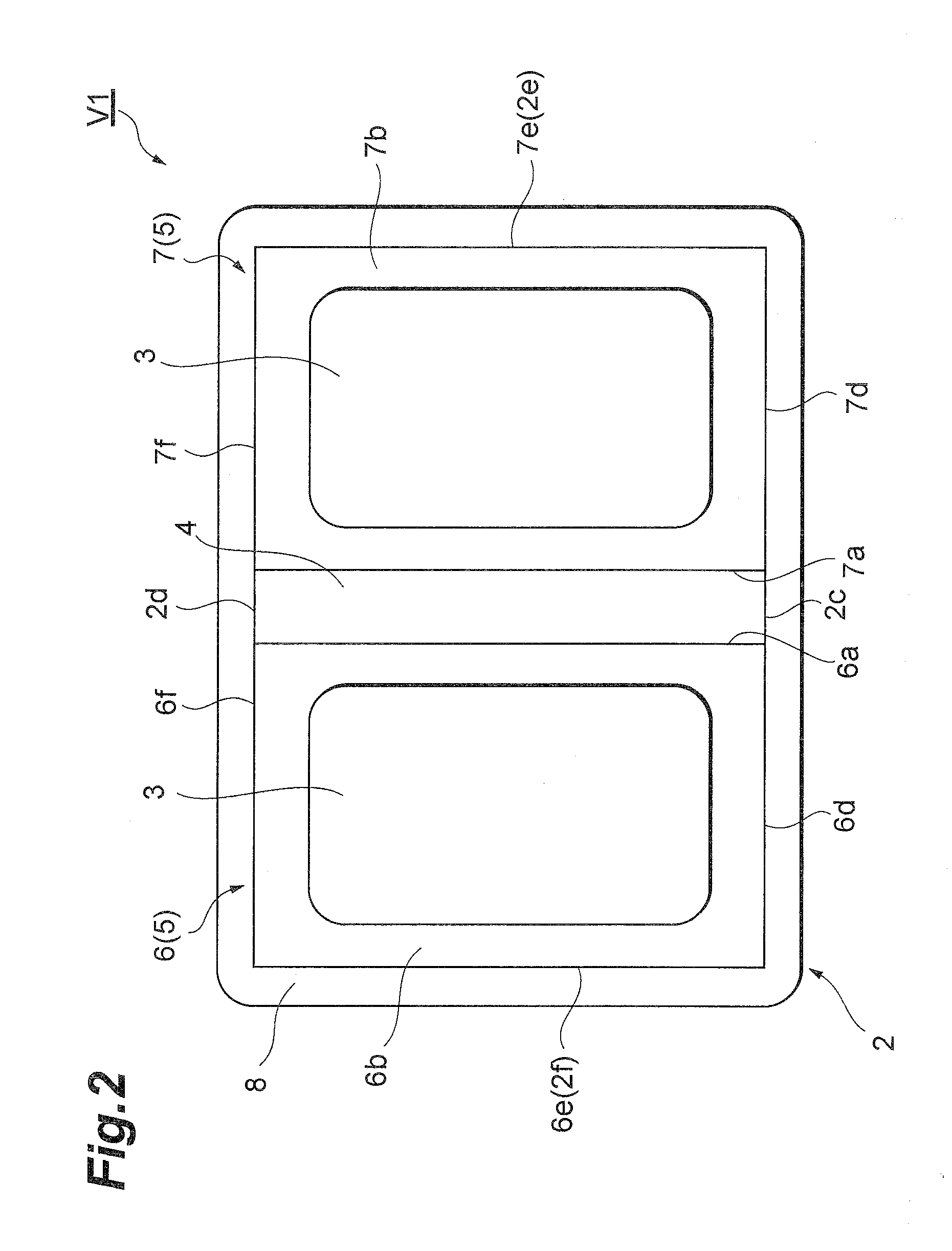
[0038]FIG. 1 is a perspective view illustrating the varistor in accordance with the first embodiment of the present invention. FIG. 2 is a plan view of the varistor illustrated in FIG. 1, while FIG. 3 is a sectional view taken along the line III-III of FIG. 1 and illustrates a state mounted with a semiconductor light-emitting device. As illustrated in FIGS. 1 to 3, this varistor V1 comprises a varistor matrix (ceramic matrix) 2 and a pair of outer electrodes 3, 3.

[0039]The varistor matrix 2 is substantially formed like a rectangular parallelepiped and has main faces (first and second main faces) 2a, 2b opposing each other and four side faces 2c to 2f orthogonal to the main faces 2a, 2b. The varistor matrix 2 is constituted by a varistor part 4 and a composite part 5.

[0040]The varistor part 4 is a part which exhibits a voltage nonlinear characteristic between the outer electrodes 3, 3 and is formed by a semiconductor ceramic containing ZnO as a main ingredient and Pr or Bi as an acce...

second embodiment

[0062]FIG. 6 is a sectional view illustrating the varistor in accordance with the second embodiment of the present invention. As illustrated in this drawing, the varistor V2 in accordance with the second embodiment further comprises outer electrodes 23, 23 formed on the main face 2b, which makes it different from the first embodiment having no outer electrodes on the main face 2b of the varistor matrix 2.

[0063]That is, in the varistor V2, the outer electrodes 23, 23 are formed such as to come into contact with the side faces 6c, 7c of the first and second portions 6, 7 of the composite part 5 exposed at the main face 2b of the varistor matrix 2. The outer electrodes 23, 23 are arranged such as to oppose the outer electrodes 3, 3 on the main face 2a. On the main face 2a of the varistor matrix 2, the part free of the outer electrodes 3, 3 is formed with the insulating material 9.

[0064]Such a varistor V2 can also yield operations and effects similar to those of the varistor V1 in accor...

third embodiment

[0065]FIG. 7 is a sectional view illustrating the varistor in accordance with the third embodiment of the present invention. As illustrated in this drawing, the varistor V3 in accordance with the third embodiment has a varistor part 34 formed with first and second inner electrodes 31, 32 opposing each other, which makes it different from the first embodiment free of the first and second inner electrodes 31, 32.

[0066]That is, the varistor part 34 of the varistor V3 has a first inner electrode 31 arranged along a part where the varistor part 34 and the first portion 6 of the composite part 5 are in contact with each other and a second inner electrode 32 arranged along a part where the varistor part 34 and the second portion 7 of the composite part 5 are in contact with each other.

[0067]The first and second inner electrodes 31, 32 are formed by a metal such as an Ag—Pd alloy, for example, and have a thermal conductivity which is several to several ten times that of ZnO which is a main ...


PUM


Abstract

A varistor having a favorable heat-dissipating property is provided.
In the varistor, a composite part having a favorable heat-dissipating property formed by a composite material composed of ZnO and Ag is arranged between main faces of a varistor matrix. Therefore, the heat transmitted from a semiconductor light-emitting device to a varistor part through an outer electrode can rapidly be transferred toward a main face on the opposite side through the composite part. In this varistor, side faces excluding inner side faces are exposed at side faces of the varistor matrix. Such a structure yields a favorable heat-dissipating property.

Description

BACKGROUND OF THE INVENTION[0001]1. Field of the Invention[0002]The present invention relates to a varistor.[0003]2. Related Background of the Invention[0004]A typical varistor comprises a varistor matrix exhibiting a voltage nonlinear characteristic and a pair of inner electrodes arranged within the varistor matrix while holding a part of the varistor matrix therebetween. A pair of outer electrodes corresponding to the inner electrodes are disposed on outer surfaces of the varistor matrix (see, for example, Japanese Patent Application Laid-Open No. 2002-246207).SUMMARY OF THE INVENTION[0005]A varistor is connected in parallel to an electronic device such as a semiconductor light-emitting device or an FET (Field Effect Transistor) and protects the electronic device against ESD (Electrostatic Discharge) surges. However, many of electronic devices generate heat during their operations. At high temperatures, the electronic devices themselves deteriorate their characteristics, thereby a...

Claims


Application Information

Patent Timeline
Patent Type & Authority Applications(United States)
IPC IPC(8): H01C7/10
CPCH01C7/1006H01C7/108H01L23/62H01L23/647H01L33/641H01L2224/16268H01L2924/1305H01L2924/01046H01L2924/01079H01L2924/09701H01L2924/00H01L2224/0554H01L2224/05568H01L2224/05573H01L2924/00014H01L2224/05599H01L2224/0555H01L2224/0556
Inventor SATO, HIROYUKINUMATA, MAKOTOSAITO, YOTANAKA, HITOSHITAKEUCHI, GOROTAGUCHI, OSAMUTANAKA, RYUICHI
Owner TDK CORPARATION
Why Eureka
Try Eureka