Position indicator, variable capacitor and input device

a variable capacitor and input device technology, applied in the direction of variable capacitors, pulse techniques, instruments, etc., can solve the problems of high manufacturing cost, difficult to reduce the outer diameter of the variable capacitor, and uncertain that the variable capacitor disclosed in patent document 2 exhibits sufficiently good characteristics, etc., to reduce the size reduce the inner diameter of the position indicator, and simplify the configuration of the variable capacitor

Inactive Publication Date: 2010-05-13
WACOM CO LTD
View PDF8 Cites 28 Cited by
  • Summary
  • Abstract
  • Description
  • Claims
  • Application Information

AI Technical Summary

Benefits of technology

[0020]According to the present invention, it is possible to simplify the configuration of a variable capacitor that constitutes a pen-pressure

Problems solved by technology

Further, in the variable capacitor disclosed in Patent Document 1 (refer to FIG. 2 of Patent Document 1), since a double-housing is used as the entire configuration, it is difficult to reduce the outer diameter of the variable capacitor.
Further, since a precision forming process needs to be employed to produce the double-housin

Method used


Image

  • Position indicator, variable capacitor and input device
  • Position indicator, variable capacitor and input device
  • Position indicator, variable capacitor and input device

Examples


first embodiment

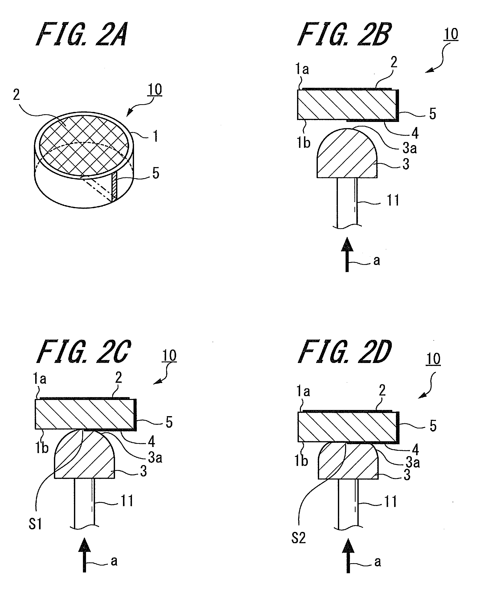
[0047]The configuration and operation principle of the variable capacitor 10, to which the present invention is applied, will be described below with reference to FIGS. 2A to 2D. FIG. 2A is a top view showing the variable capacitor 10 to which the present invention is applied, FIG. 2B is a side view showing the same, and FIG. 2C is a side view showing the same when a pen pressure is applied.

[0048]The electrode 2 is arranged on the upper surface 1a of the dielectric 1, the electrode 2 having a predetermined area. The electrode 2 is connected to the resonant capacitor 15a of the circuit board 15. Further, the conductive portion 4 is provided on the lower surface 1b of the dielectric 1, and a connecting terminal 5 is provided on a third surface 1c (referred to as “circumferential surface” hereinafter) of the dielectric 1. In the present embodiment, the electrode 2, the conductive portion 4 and the connecting terminal 5 are formed by sintering a silver paste for example.

[0049]The conduc...

second embodiment

[0117]Next, the dielectric according to the present invention will be described below with reference to FIG. 14.

[0118]The second embodiment of the dielectric is denoted by reference numeral 51. The dielectric 51 includes a first dielectric member 51A and a second dielectric member 51B. The two dielectric members 51A, 51B are formed by dividing a flat cylindrical shape dielectric into two in the axial direction, and have the same shape. In other words, the flat cylindrical shape dielectric 51 is formed by arranging the two dielectric members 51A, 51B in the planar direction.

[0119]An electrode 56A is provided on a first surface (referred to as “upper surface” hereinafter) 52 of the first dielectric member 51A. The electrode 56A has a semicircular shape that covers substantially the whole upper surface 52 of the first dielectric member 51A. Further, a conductive portion (not shown) and a connecting terminal (not shown) are provided on the first dielectric member 51A. The conductive por...


PUM


Abstract

A variable capacitor of a position indicator includes a dielectric, an electrode, a conductive member and a conductive portion. The dielectric has an upper surface and a lower surface opposite the upper surface. The electrode is provided on the upper surface of the dielectric. The conductive member is arranged so as to face the lower surface of the dielectric. The conductive portion is provided on the lower surface of the dielectric and is arranged so as to be electrically connectable to the conductive member. The conductive member is adapted to be elastically deformed when pressed against the lower surface by an external force, such that the capacitance of the variable capacitor changes according to a change of the external force.

Description

CROSS REFERENCES TO RELATED APPLICATIONS[0001]The present invention claims the benefit of Japanese Patent Application 2008-291433, filed in the Japanese Patent Office on Nov. 13, 2008, the entire content of which is being incorporated herein by reference.BACKGROUND OF THE INVENTION[0002]1. Field of the Invention[0003]The present invention relates to a position indicator suitable to be used to detect a pen pressure, a variable capacitor adapted to detect the pen pressure, and an input device having the position indicator.[0004]2. Description of the Related Art[0005]In recent years, a coordinate input device has been used as an input device for a personal computer for example. Such a coordinate input device is configured by a pen-like position indicator and a position detecting device having an input surface where input operation such as a pointing operation, a handwritten character input operation and a hand-drawn illustration input operation is performed by using the position indica...

Claims


Application Information

Patent Timeline
IPC IPC(8): G06F3/033H01G7/00
CPCG06F3/03545H01G5/015H01G5/0136
Inventor FUKUSHIMA, YASUYUKIFUJITSUKA, HIROYUKI
Owner WACOM CO LTD
Why Eureka
Try Eureka