Sliding bearing for internal combustion engine and sliding bearing device

a technology of sliding bearing and internal combustion engine, which is applied in the direction of sliding contact bearings, connecting rod bearings, bearing unit rigid support, etc., can solve the problems of bearing damage, abrasion or seizure, and the wiping phenomenon caused by the stepped difference cannot be avoided

Inactive Publication Date: 2010-05-13
DAIDO METAL CO LTD
View PDF6 Cites 24 Cited by
  • Summary
  • Abstract
  • Description
  • Claims
  • Application Information

AI Technical Summary

Benefits of technology

[0009]Thus, an object of the present invention is to provide a sliding bearing consisting of a pair of semi-cylindrical bearings held in a split-type bearing housing, which is capable of preventing the so-called wiping phenomenon that lubricant oil flowing along the inner surface of the sliding bearing in the same direction as that of the rotation direction of a shaft to be supported (a crank pin or a crank journal) is scraped up by a stepped difference that is though caused between abutting end faces of the sliding bearing due to a difference in bore size between both semi-cylindrical bodies.
[0030]In an ninth embodiment of the present invention, the thicknesses of the pair of semi-cylindrical bearings are adjusted in the circumferential end regions, thereby the inner surface of the semi-cylindrical bearing incorporated in the housing half having a relatively higher stiffness and the inner surface of the other semi-cylindrical bearing body incorporated in the other housing half are aligned with each other at those abutting end faces. According to such configuration, a prevention effect of occurrence of the wiping phenomenon is enhanced, so that even if the stepped difference variable under dynamic load is large, a relationship between the pair of semi-cylindrical bearings can hardly become a barrier against lubricant oil flowing in the circumferential grooves.
[0032](1) The one of the pair of bearing-housing halves constituting the split type bearing housing, which has a relatively lower stiffness, suffers a large degree of deformation in the assembled condition in comparison with the mating housing half having a relatively higher stiffness, so that the semi-cylindrical bearing incorporated in the housing half having the relatively lower stiffness suffers a relatively large degree of elastic deformation in comparison with the mating semi-cylindrical bearing incorporated in the housing half having the relatively higher stiffness. Thus, the inner diameters of both semi-cylindrical bearings at those circumferential end faces (i.e. those abutting end faces) are different from each other, so that the abutting end faces of the semi-cylindrical bearing incorporated in the housing half having the relatively higher stiffness project inwardly (i.e. toward the center axis of the sliding bearing) relative to the abutting end faces of the other semi-cylindrical bearing incorporated in the other housing half having a relatively lower stiffness.
[0033]This deviated state of the abutting end faces can be comprehended as a stepped difference, since the semi-cylindrical bearing which is incorporated in the housing half having the relatively higher stiffness projects its abutting end faces on the inner surface (sliding surface) side of the sliding bearing. In a conventional sliding bearing, the stepped difference have set off an oil scraping phenomenon (i.e. the wiping phenomenon). However, according to the present invention, since the one of the semi-cylindrical bearings which is incorporated at least in the bearing housing half having relatively higher stiffness is provided with a number of circumferential grooves on its inner surface, and since the circumferential grooves formed in an circumferential end region including at least one of two circumferential end faces of the semi-cylindrical bearing, which faces in a direction opposite to the rotation direction of the shaft to be supported, have a depth of not less than 10 μm, the lubricant oil smoothly flows along the inner surface of the sliding bearing in the rotation direction of the shaft to be supported while being guided by the circumferential grooves having a depth of not less than 10 μm without interruption by the stepped difference. Thus, it is possible to reduce an amount of the lubricant oil flowing, toward the widthwise direction of the sliding bearing, along the stepped difference in the abutting end faces of the semi-cylindrical bearings, thereby enabling an effective prevention of occurrence of damages of the sliding bearing, such as wear, seizure and so on due to an insufficient supply amount of the lubricant oil.
[0035](3) According to a third embodiment of the present invention, while ridges of the circumferential grooves serve as barriers against an oil leakage in the widthwise direction of the sliding bearing, since each of the ridges has a large cross-sectional area around those crests by making the pitch of the circumferential grooves to be not less than 0.5 mm, the ridges can have a higher strength and accordingly can hardly cause plastic deformation even though they are in contact with a mating shaft, and can hardly be worn. Thus, the clearance between the crests and the mating shaft to be supported can be prevented from being increased, thereby it is possible to prevent the quantity of leakage of the lubricant oil widthwise of the sliding bearing from being increased. On the other hand, if the pitch of the circumferential grooves is less than 0.5 mm, since the ridges have smaller cross-sectional areas around those crests, the ridges have a lower strength, and accordingly, they readily cause plastic deformation and are quickly worn when they are in contact with the associated shaft. Further, if the pitch of the circumferential grooves exceeds the upper limit of 1.5 mm, the number of the ridges becomes excessively small, and accordingly, a surface contact pressure between the ridges and the mating shaft at the crests becomes higher resulting in an increased wear amount.
[0038](6) In the fifth to ninth embodiments of the present invention, the thickness of the pair of semi-cylindrical bearings is adjusted in those circumferential end regions so that the inner surface of the semi-cylindrical bearing incorporated in the one housing half is aligned with the inner surface of the other semi-cylindrical bearing incorporated in the other housing half, at those abutting end faces. According to such a configuration, the effect of preventing occurrence of the wiping phenomenon is enhanced, and such an effect is obtainable even if large stepped differences occurred due to a dynamic load thereby enabling the pair of combined semi-cylindrical bearings not to interrupt a flow of the lubricant oil in the circumferential grooves.

Problems solved by technology

As a result, the quantity of leakage of the oil from both widthwise ends of the sliding bearing increases, and accordingly, the supply quantity of the lubricant oil onto the inner surface (that is, the sliding surface) of the sliding bearing becomes insufficient, resulting in damage to the bearing, such as abrasion or seizure.
Even using the above-mentioned configuration, the dynamic load which is exerted on the split type bearing housing during operation of the internal combustion engine causes elastic deformations of the bearing cap and the associated housing, which are different from each other since the bearing cap and the associated housing have different stiffness from each other, and accordingly, occurrence of stepped difference between the abutting end faces of the sliding bearing, and the wiping phenomenon caused by the stepped difference cannot be avoided.

Method used


Image

  • Sliding bearing for internal combustion engine and sliding bearing device
  • Sliding bearing for internal combustion engine and sliding bearing device
  • Sliding bearing for internal combustion engine and sliding bearing device

Examples


invention examples 1 to 4

(1) Invention Example 1

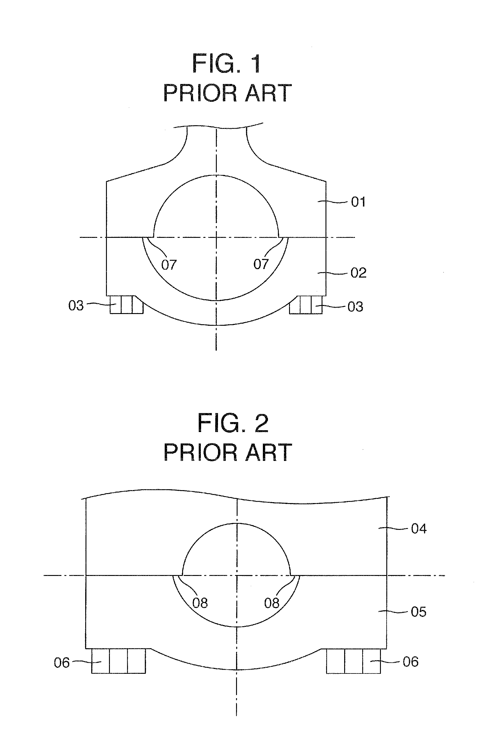
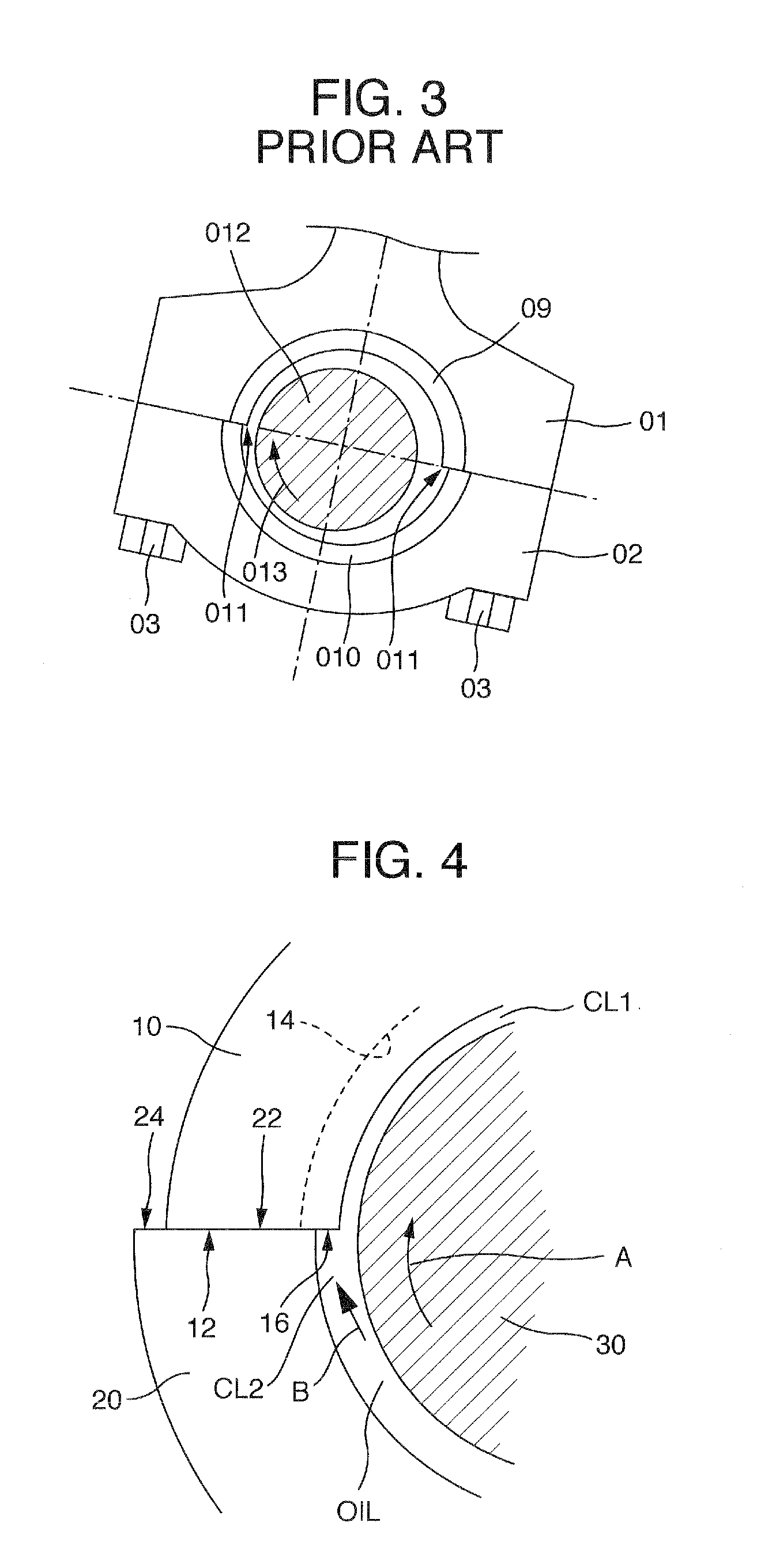
[0063]The circumferential grooves, having a depth of not less than 10 μm and a pitch of 0.5 to 1.5 mm, are formed throughout on the inner surface of a semi-circular bearing which is held on the big end part of a connecting rod. However, no circumferential grooves are formed on the inner surface of a semi-circular bearing which is held in a bearing cap. When the bearing cap is assembled to the big end part of the connecting rod by fastening bolts after the pair of semi-cylindrical bearings are combined with each other, the inner surface of the semi-cylindrical bearing held by the bearing cap is expanded outwardly in the circumferential end regions thereof as shown in FIGS. 4 and 8.

example 2

(2) Invention Example 2

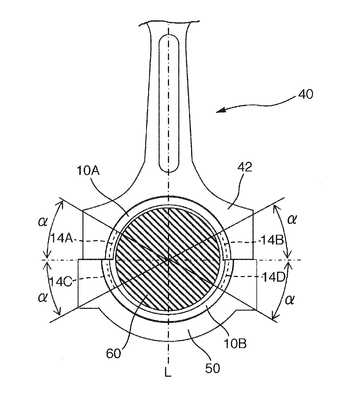
[0064]The circumferential grooves having a depth of not less than 10 μm and a pitch of 0.5 to 1.5 mm are formed in the inner surface of a semi-cylindrical bearing which is held in the big end part of the connecting rod, in both circumferential end regions having an extent of a circumferential length corresponding to a circumferential angle α=10 to 50°. On the other hand, the surface roughness of not more than 3.2 μmRz is provided on the inner surface (i.e. a main load bearing region) except for the both circumferential end regions. No circumferential grooves are formed on the inner surface of a semi-cylindrical bearing held in a bearing cap. When the bearing cap is combined to the big end part of the connecting rod by means of fastening bolts after the pair of semi-cylindrical bearings are combined with each other, the circumferential end regions of the inner surface of the semi-cylindrical bearing held by the bearing cap is expanded outwardly in the circumfer...

example 3

(3) Invention Example 3

[0065]The circumferential grooves having a depth of not less than 10 μm and a pitch of 0.5 to 1.5 mm are formed throughout on the inner surface of a semi-cylindrical bearing which is held in the big end part of a connecting rod. However, no circumferential grooves are formed in the inner surface of the other semi-cylindrical bearing which is held by a bearing cap. When the bearing cap is combined to the big end part of the connecting rod by means of fastening bolts after the pair of semi-cylindrical bearings are assembled with each other, the circumferential end regions of the inner surface of the semi-cylindrical bearing held by the bearing cap is expanded outwardly in the circumferential end regions thereof, as shown in FIGS. 4 and 8.


PUM


Abstract

Disclosed is a sliding bearing consisting of a pair of semi-cylindrical bearings for supporting a crankshaft or a crank pin in an internal combustion engine. The sliding bearing is incorporated in a split-type bearing housing. One of the semi-cylindrical bearings being incorporated in at least one of the pair of housing halves, which one housing half has a relatively higher stiffness, is provided with a number of circumferential grooves on an inner surface of the semi-cylindrical bearing so as to extend circumferentially along the inner surface of the semi-cylindrical bearing. The circumferential grooves existing at least one circumferential end region of the inner surface of the semi-cylindrical bearing have a depth of not less than 10 μm, the circumferential end region including a circumferential bearing end face orientating a direction opposite to the rotation direction of the shaft or pin.

Description

CROSS-REFERENCE TO RELATED APPLICATIONS[0001]The present application claims priority from JP Patent Application Ser. No. 2008-289730 filed on Nov. 12, 2008, the content of which is hereby incorporated by reference into this application.TECHNICAL BACKGROUND OF THE INVENTION[0002]The present invention relates to a sliding bearing consisting of a pair of semi-cylindrical bearings combined with each other so as to form a cylinder, for supporting a crankshaft or a crank pin in an internal combustion engine, the semi-cylindrical bearings being adapted to be incorporated in a split-type bearing housing having a cylindrical bearing retaining bore which is bi-split so as to correspond to the cylindrically combined semi-cylindrical bearings. (Refer to JP-A-08-210355 for example.)RELATED ART[0003]A sliding bearing for supporting a crank journal or a crank pin in an internal combustion engine has been used in the form of a cylindrical member consisting of a pair of combined semi-cylindrical bea...

Claims


Application Information

Patent Timeline
Patent Type & Authority Applications(United States)
IPC IPC(8): F16C9/02
CPCF16C9/02F16C33/107F16C2360/22F16C2240/54F16C33/046F16C2240/42F16C9/04F16C17/022F16C17/028F16C9/00
Inventor ISHIGO, OSAMUOKADO, ATSUSHI
Owner DAIDO METAL CO LTD
Why Eureka
Try Eureka