Device for regulating the flow rate of air feeding a turbine ventilation cavity of a turbomachine turbine section

a technology of turbine ventilation cavity and turbine section, which is applied in the direction of efficient propulsion technologies, machines/engines, engine starters, etc., can solve the problems of too much air being taken off during such speeds of operation and the inability to regulate the flow rate of air being taken off, etc., and achieve the effect of reducing such drawbacks

Active Publication Date: 2010-05-13
SN DETUDE & DE CONSTR DE MOTEURS DAVIATION S N E C M A
View PDF6 Cites 23 Cited by
  • Summary
  • Abstract
  • Description
  • Claims
  • Application Information

AI Technical Summary

Benefits of technology

[0017]As a result, the device of the invention serves to regulate the flow rate of air for providing ventilation of a turbine section as a function of the operating point of the turbomachine. This results in optimized take-off of air from the compressor. For a given thrust level, fuel consumption can be reduced compared with a prior art take-off device. More precisely, for a two-spool bypass turbomachine, the savings in terms of specific consumption are estimated at around 0.3%.
[0018]The device of the invention also presents the advantage of being of simple and reliable design, of not requiring any particular power supply circuit, and above all of presenting very low weight.
[0019]In an advantageous disposition, the device further includes means for completely closing the duct when the pressure inside the duct becomes significantly lower than the pressure inside turbine ventilation cavity. Such means make it possible, in the event of the duct being accidentally broken, to prevent the gas stream flowing in the primary flow section of the turbine escaping therefrom.

Problems solved by technology

Nevertheless, taking compressed air to deliver it to the turbine ventilation cavity via ducts provided with flow rate calibration diaphragms as described above, does not enable the flow rate of the air that is taken off to be regulated as a function of the operating speed of the turbomachine.
In flight at a lower speed of operation, where temperature levels in the turbomachine are not so high (such as when cruising), a smaller air flow rate would be sufficient for ventilating the turbines, so as a result too much air is taken off during such speeds of operation.
Unfortunately, the air that is taken from the compressor and reintroduced further downstream into the turbine at a location where the pressure level is lower does less work in the turbine than it would have done if it had not been taken off.
This has the consequence of penalizing fuel consumption.

Method used


Image

  • Device for regulating the flow rate of air feeding a turbine ventilation cavity of a turbomachine turbine section
  • Device for regulating the flow rate of air feeding a turbine ventilation cavity of a turbomachine turbine section
  • Device for regulating the flow rate of air feeding a turbine ventilation cavity of a turbomachine turbine section

Examples


Embodiment Construction

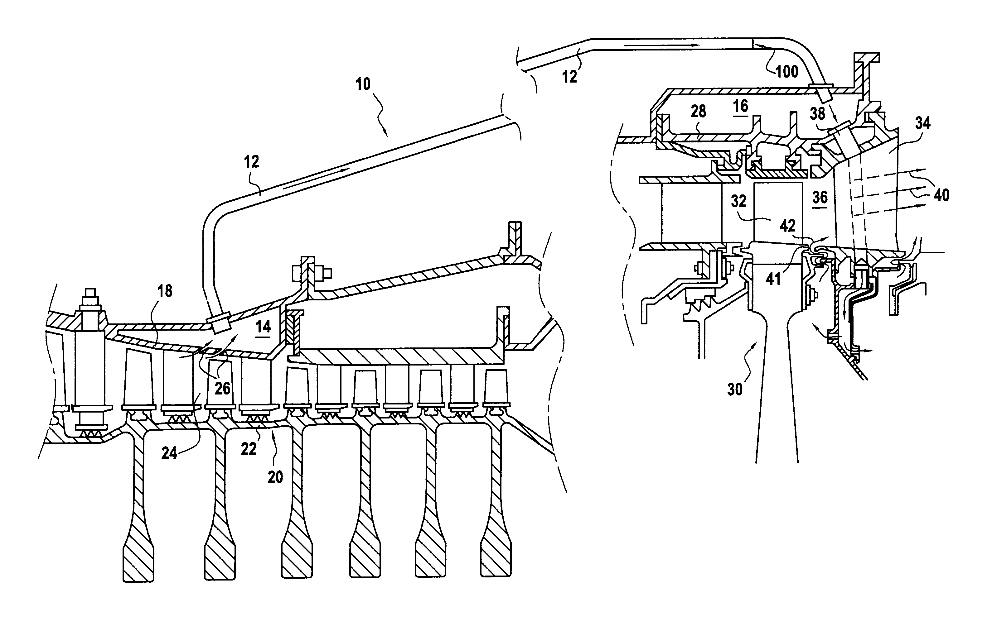
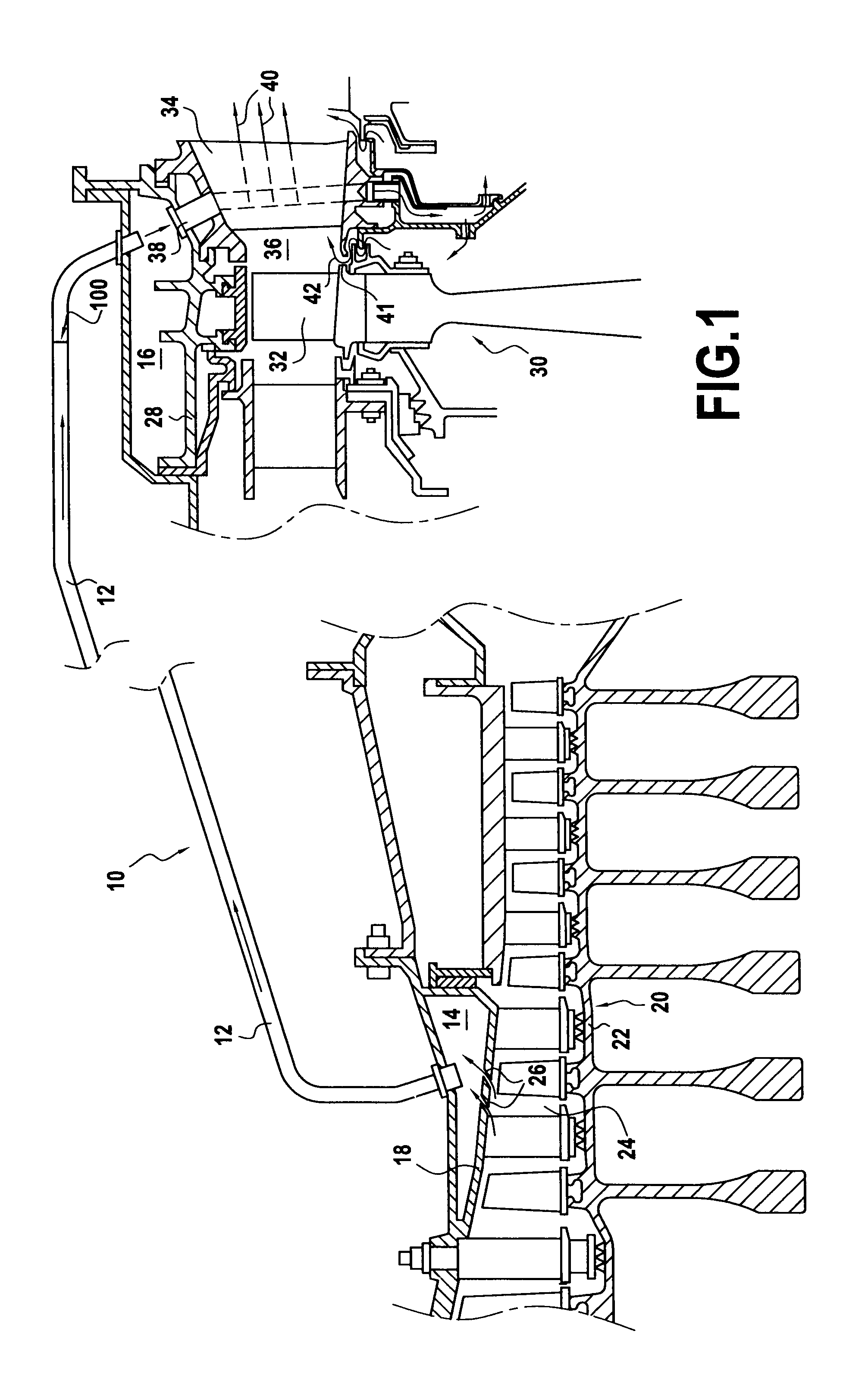
[0032]FIG. 1 shows a portion of a device 10 in accordance with the invention for regulating the flow of air that is to purge and cool certain parts of high and low pressure turbines in an aviation turbomachine.

[0033]Naturally, the invention applies more generally to any air take-off device made by means of tubes and presenting pressure differences between the air take-off zone and the air re-insertion zone.

[0034]The device of the invention comprises a plurality of tubular ducts 12 (only one is shown in FIG. 1), each duct opening at an upstream end into a take-off cavity 14 and leading at an opposite, downstream end to a turbine ventilation cavity 16.

[0035]The take-off cavity 14 is an annular cavity formed around the outer shroud 18 of the high stream compressor 20 of the turbomachine. An inner shroud 22 disposed concentrically inside the outer shroud co-operates therewith to define a flow passage 24 for a stream of air passing through the high pressure compressor. The take-off cavit...


PUM


Abstract

The invention relates to a device for regulating the flow rate of air feeding a turbine ventilation cavity of a turbomachine turbine section, the device comprising at least one tubular duct opening into a take-off cavity and leading into a turbine ventilation cavity, the pressure inside the take-off cavity being higher than the pressure inside the turbine ventilation cavity, an air flow rate regulation valve disposed in the tubular duct, the valve being suitable for moving under the effect of the pressure difference between the take-off cavity and the turbine ventilation cavity, and mechanical return means for holding the valve in a maximum closure position for the duct so long as the pressure difference between the take-off cavity and the turbine ventilation cavity remains below a predetermined threshold pressure.

Description

BACKGROUND OF THE INVENTION[0001]The invention relates to the general field of ventilating a turbine section of a turbomachine. The invention relates more particularly to a device for regulating the flow rate of air for feeding to a turbine ventilation cavity in a turbine section of an aviation turbomachine.[0002]In the present description, the term “ventilating” is used in respect of a turbine section to cover both a function of cooling the various vanes and / or blades of the turbine section, and a purging function to prevent hot air in the primary flow passage through the turbine from being reintroduced elsewhere.[0003]When an aviation turbomachine is operating at high speed (typically at full throttle), the temperatures of the gases flowing in the primary flow passage of the turbomachine reach values that cannot be withstood without damage by the parts situated outside said passage, in particular parts situated around the turbine section(s) of the turbomachine (low pressure turbin...

Claims


Application Information

Patent Timeline
Patent Type & Authority Applications(United States)
IPC IPC(8): F01D17/00
CPCF01D9/065F01D17/145F02C6/08F05D2260/205Y02T50/676F05D2270/3015F16K15/038Y02T50/60Y10T137/7839Y10T137/7848
Inventor FINTESCU, IONGILLE, LAURENTMOURLAN, JEAN-PIERRE ANDRE JOSEPHSAVARIT, MATTHIEU
Owner SN DETUDE & DE CONSTR DE MOTEURS DAVIATION S N E C M A
Why Eureka
Try Eureka