Methods and apparatus for dynamically compensating for DC offset drift and other pvt-related signal variations in polar transmitters

a technology of polar transmitters and power amplifiers, applied in the field of switchmode power amplifiers (pas) and polar transmitters, can solve the problems of not being subject to temperature related sorting procedures nor the use of thermal probes, and achieve the effects of simple calibration loop, simple factory calibration, and energy saving

Active Publication Date: 2010-05-13
PANASONIC CORP
View PDF5 Cites 67 Cited by
  • Summary
  • Abstract
  • Description
  • Claims
  • Application Information

AI Technical Summary

Benefits of technology

[0014]The methods and apparatus of the present invention have various advantages and benefits over other DC offset drift compensation approaches. First, they do not rely on models, characterizations, or estimates. Second, they neither require the use of a thermal probe nor are subject to temperature related sorting procedures. Third, the ability to dynamically adjust the magnitude and / or amplitude of signals during operation, to counter DC offset drift and other PVT-related influences, greatly simplifies factory calibration. Only a limited number of power measurements at ambient temperature need to be taken and recorded. Fourth, the methods and apparatus of the present invention do not require a closed-loop polar architecture. Instead, all that is needed to perform the compensation methods of the present invention is the addition of a simple calibration loop. Hence, the benefits of open-loop polar architectures can continue to be enjoyed. Finally, although not lastly, the methods and apparatus of the present invention are computationally efficient, energy efficient and flexible. In many circumstances, compensation for DC offset drift and / or other PVT-related signal variations can be accomplished based on a single digital sample of the detector output. This reduces the computational load of the baseband processor and conserves energy. Nevertheless, multiple-sample processing remains available, to provide flexibility and achieve higher compensation accuracy if it is desired.

Problems solved by technology

Second, they neither require the use of a thermal probe nor are subject to temperature related sorting procedures.

Method used


Image

  • Methods and apparatus for dynamically compensating for DC offset drift and other pvt-related signal variations in polar transmitters
  • Methods and apparatus for dynamically compensating for DC offset drift and other pvt-related signal variations in polar transmitters
  • Methods and apparatus for dynamically compensating for DC offset drift and other pvt-related signal variations in polar transmitters

Examples


Embodiment Construction

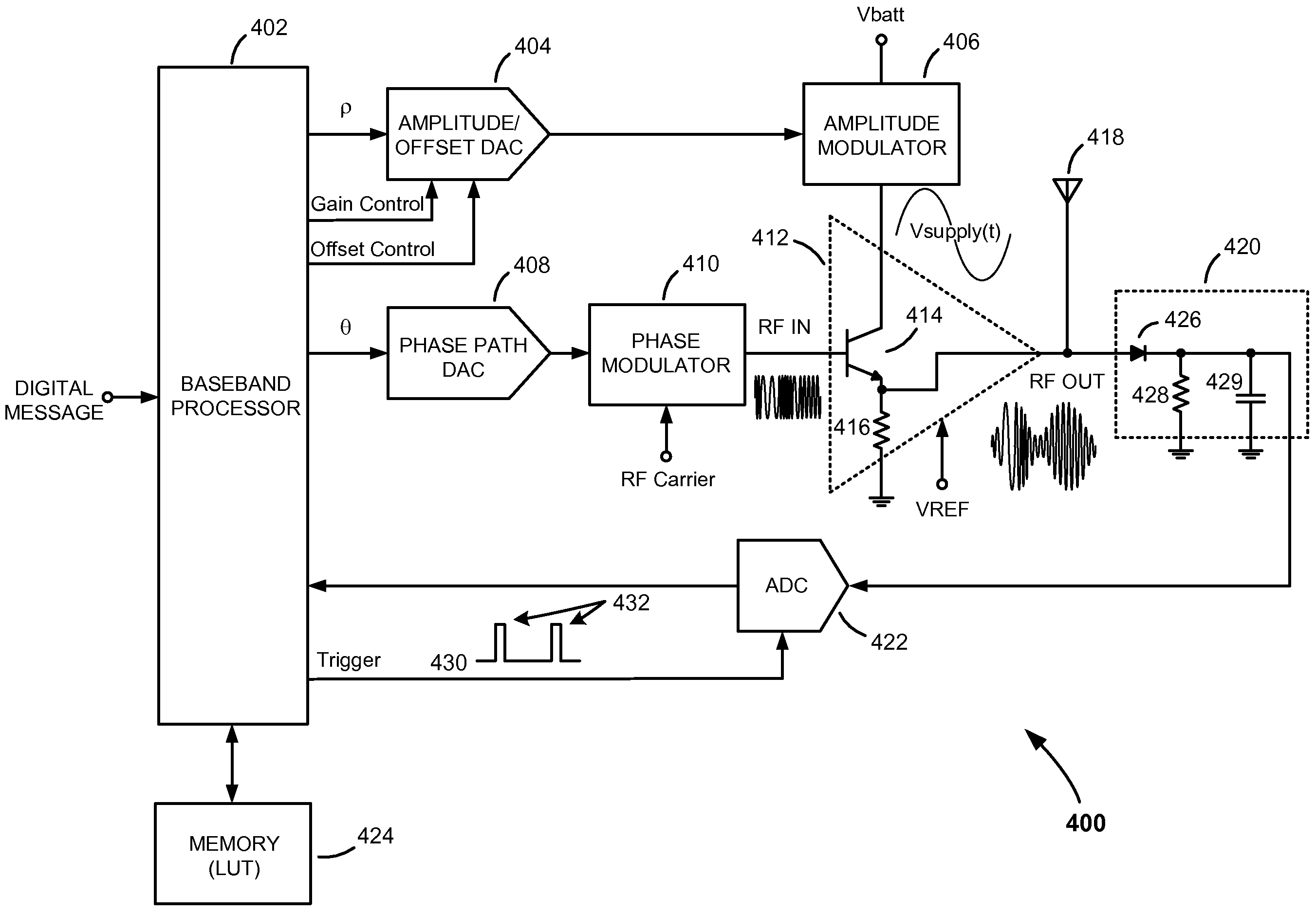
[0025]The present invention is directed at methods and apparatus that dynamically compensate for direct current (DC) offset drift and other process-voltage-temperature (PVT)-related signal variations in switch-mode power amplifiers (PAs) and in polar transmitters employing switch-mode PAs. The exemplary embodiments of the invention are described in the context of compensating for DC offset drift and other undesired signal variations in switch-mode radio frequency PAs (RFPAs) employed in RF polar transmitters. However, the methods and apparatus are not limited to power applications, to polar transmitters, or to wireless transmitters. They may be adapted for use in non-power applications, are applicable to other types of transmitters (i.e., other than polar transmitters) that employ switch-mode RFPAs, and may be adapted for use in wired transmitters, such as wired transmitters configured to transmit over a fiber optic link. Further, although the methods and apparatus of the present in...


PUM


Abstract

Methods and apparatus for dynamically compensating for signal variations in communications transmitters employing switch-mode PAs. An exemplary method includes first identifying a predetermined signal characteristic in an input signal applied to an input of a switch-mode PA. A modulated signal produced at the output of the switch-mode PA containing the identified signal characteristic is then sampled at approximately the same time the identified signal characteristic appears at the output of the switch-mode PA, to generate a digital sample representing an actual value of the identified signal characteristic. An error signal representing the extent to which the actual value deviates from an expected value is then generated. Finally, the DC level and / or gain of the input signal to the switch-mode PA is modified to reduce the error. By reducing the error in this manner, signal variations that adversely affect the accuracy of the switch-mode PA output signal are dynamically compensated for.

Description

FIELD OF THE INVENTION[0001]The present invention relates to switch-mode power amplifiers (PAs) and polar transmitters. More specifically, the present invention relates to methods and apparatus for dynamically compensating for direct current (DC) offset drift in switch-mode PAs, and compensating for other process-voltage-temperature (PVT) related signal variations in polar transmitters.BACKGROUND OF THE INVENTION[0002]Wireless communication devices, such as cellular handsets and wireless personal digital assistants, continue to gain widespread use in today's world. With each new generation of wireless communication technology, they have become more technically sophisticated, now commonly providing or supporting, in addition to traditional voice communications, text messaging, electronic mail, mini browsers for surfing the Internet, etc. While users no doubt enjoy the benefits these additional features provide, the additional features can seriously impact battery life.[0003]Efforts t...

Claims


Application Information

Patent Timeline
Patent Type & Authority Applications(United States)
IPC IPC(8): H01Q11/12H04L25/03
CPCH03F1/0261H03F1/3247H04L27/368H03F3/245H04L27/362H03F3/217
Inventor PENNEC, CHRISTIAN
Owner PANASONIC CORP
Why Eureka
Try Eureka