
Boot for constant-velocity universal joint and cross-grooved constant-velocity universal joint

a constant-velocity universal joint, cross-groove technology, applied in the direction of couplings, mechanical devices, rod connections, etc., can solve the problems of high cost of boots and large amount of grease to be filled within boots, and achieve the effect of suppressing deformation and suppressing deformation

Inactive Publication Date: 2010-05-13
JTEKT CORP +1
View PDF12 Cites 11 Cited by
  • Summary
  • Abstract
  • Description
  • Claims
  • Application Information

AI Technical Summary

Benefits of technology

[0009]However, in the case of using boots that have rigidity being equal to that of the metallic fitting (FIG. 1 of Japanese Unexamined Utility Model Publication (KOKAI) Gazette No. 1-69, 916), the axial length should be secured sufficiently in addition to the wall thickness in order to secure high rigidity for the aforesaid boots. By means of thus making the wall thickness thicker and the axial length longer, the volume of elastomer for forming the boots enlarges. Therefore, it brings about making the boots high cost. Further, by means of the fact that the axial length of the boots enlarges, the boots themselves jumboize; as a result, the grease to be filled within them becomes necessary in a large amount. Moreover, in the technique according to Japanese Unexamined Utility Model Publication (KOKAI) Gazette No. 1-69, 916, the rigid cylindrical portion has a cylindrical configuration. There has been such a desire that one would like to enhance the rigidity further by devising the configuration of such a rigid cylindrical portion and consequently to enhance the rigidity at around the major-diameter cylindrical portion furthermore, thereby suppressing the coming off of the balls that results from the deformed boots. Moreover, in the case of using another component part, such as the metallic fitting and circlip (FIG. 2 of Japanese Unexamined Utility Model Publication (KOKAI) Gazette No. 1-69, 916, and Japanese Unexamined Utility Model Publication (KOKAI) Gazette No. 6-32, 755), it brings about turning them into high-cost ones by means of the increase in the number of component-part quantities and the increase in the number of man-hour requirements for assembly.
[0012]In accordance with the aforementioned construction, the rigidity-producing portion exhibits a diameter that enlarges from the bellows portion toward the major-diameter cylindrical portion, and additionally at least an outer peripheral surface of the rigidity-producing portion has a plurality of shoulders in a stepwise manner. The rigidity-producing portion with a plurality of shoulders being formed in a stepwise manner exhibits rigidity higher than that of rigidity-producing portion with cylindrical configuration. Accordingly, it is possible to enhance rigidity at around the major-diameter cylindrical portion. That is, by means of turning the vicinity of the major-diameter cylindrical portion into the rigidity-producing portion possessing a plurality of stepwise shoulders, the rigidity at around the major-diameter cylindrical portion enhances, compared with the case of forming the same part as that of the rigidity-producing portion as a cylindrical shape, a cup shape or a bellows shape in a boot with identical size. Because of this, even when the resultant universal joint is raised, it is possible to keep the boot from deforming downward due to the weight of outer race, and thereby it is possible to keep balls from coming off from the outer race.
[0014]In accordance with said construction, the boot exhibits a diameter that enlarges from the bellows portion toward the major-diameter cylindrical portion, and additionally possesses the rigidity-producing portion that has a plurality of shoulders in a stepwise manner on at least an outer peripheral surface of the rigidity-producing portion. Accordingly, it is possible to enhance rigidity at around the major-diameter cylindrical portion. Therefore, even when the resultant universal joint is raised, it is possible to keep the boot from deforming downward due to the weight of the outer race, and thereby it is possible to keep the balls from coming off from the outer race.EFFECT OF THE INVENTION
[0016]In accordance with the cross-grooved constant-velocity universal joint according to the present invention, since it is provided with the boot that possesses said rigidity-producing portion in the vicinity of the major-diameter cylindrical portion, the rigidity at around the major-diameter cylindrical portion enhances. Hence, it is possible to suppress deformation at the time of assembly, and thereby it is possible to prevent the balls from coming off from the outer race.

Problems solved by technology

Therefore, it brings about making the boots high cost.
Further, by means of the fact that the axial length of the boots enlarges, the boots themselves jumboize; as a result, the grease to be filled within them becomes necessary in a large amount.

Method used


Image

  • Boot for constant-velocity universal joint and cross-grooved constant-velocity universal joint
  • Boot for constant-velocity universal joint and cross-grooved constant-velocity universal joint
  • Boot for constant-velocity universal joint and cross-grooved constant-velocity universal joint

Examples


embodiments

[0059]Hereinafter, the present invention will be explained concretely by means of embodiments and comparative examples.

embodiment no.1

Embodiment No. 1

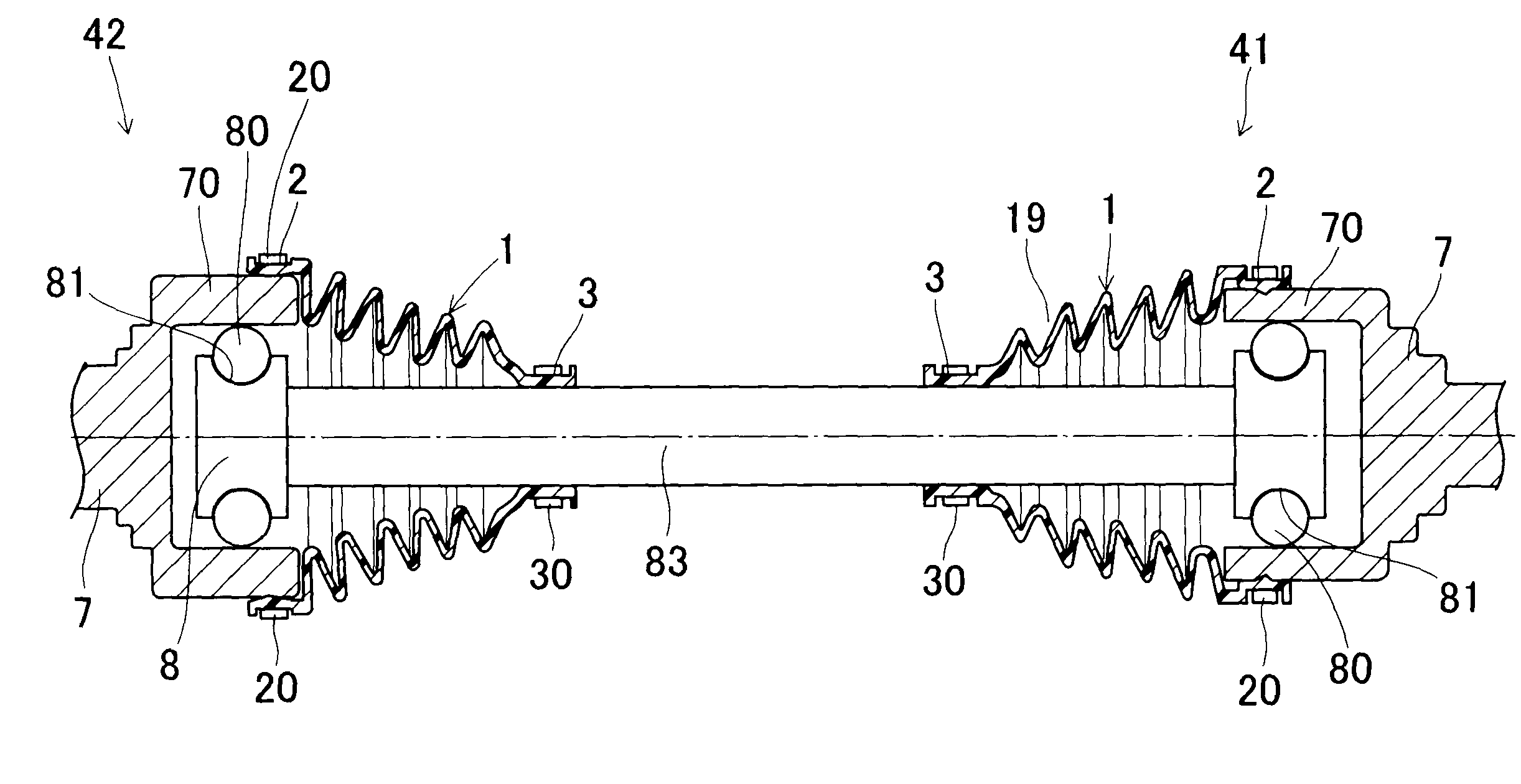
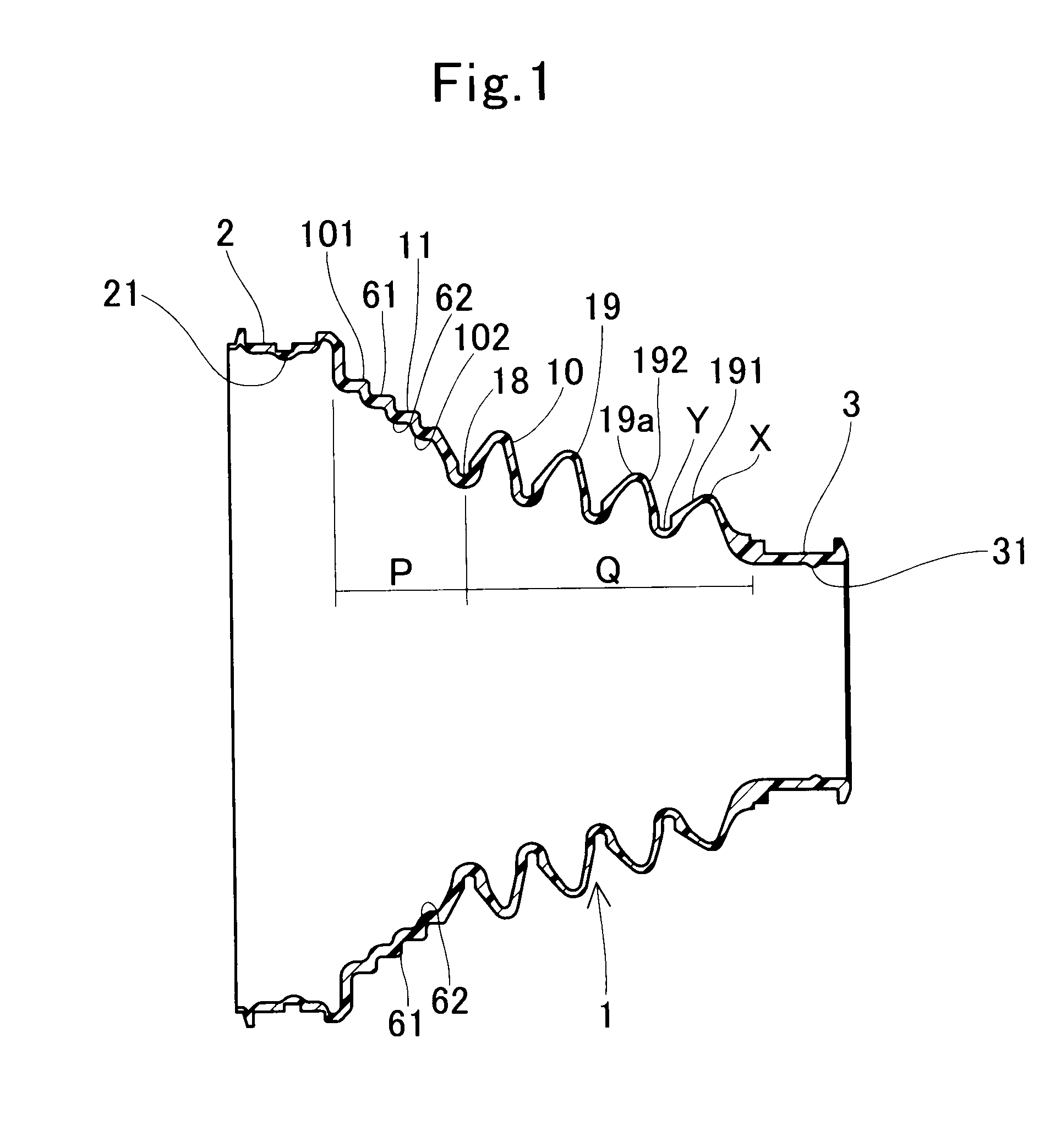
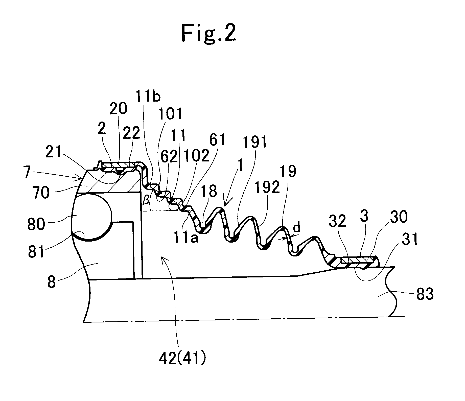
[0060]As illustrated in FIG. 1 and FIG. 2, a boot 1 for constant-velocity universal joint that is directed to one of embodiments according to the present invention comprises: a major-diameter cylindrical portion 2; a minor-diameter cylindrical portion 3 being separated away from and being put in place concentrically with the major-diameter cylinder portion 2, and having a smaller diameter than that of the major-diameter cylindrical portion 2; and a substantially-truncated-cone-configured intermediate portion 10 connecting the major-diameter cylindrical portion 2 with the minor-diameter cylindrical portion 3. The intermediate portion 10 comprises: a stretchable bellows portion 19 being connected with the minor-diameter cylindrical portion 3 integrally; and a rigidity-producing portion 11 being connected with the bellows portion 19 and the major-diameter cylindrical portion 2 integrally. The rigidity-producing portion 11 enlarges diametrically from the bellows portion ...

embodiment no.2

Embodiment No. 2

[0070]As illustrated in FIG. 4, in a boot for constant-velocity universal joint according to the present example, the shoulders 61 on the outer peripheral surface 101 of a rigidity-producing portion 12 protrude diametrically more than those of Embodiment No. 1 do, and thereby the side surfaces 611 of the shoulders 61 incline with respect to the axial direction. The end surfaces 612 of the shoulders 61 are parallel to the diametrical direction. The others are the same as those of Embodiment No. 1.


PUM


Abstract

A boot for constant-velocity universal joint comprises a major-diameter cylindrical portion 2, a minor-diameter cylindrical portion 3 being separated away from and being put in place concentrically with the major-diameter cylinder portion 2, and having a smaller diameter than that of the major-diameter cylindrical portion 2, and an intermediate portion 10 connecting the major-diameter cylindrical portion 2 with the minor-diameter cylindrical portion 3. The intermediate portion 10 comprises a stretchable bellows portion 19 being connected with the minor-diameter cylindrical portion 3 integrally, and a rigidity-producing portion 11 being connected with the bellows portion 19 and the major-diameter cylindrical portion 2 integrally. The rigidity-producing portion 11 enlarges diametrically from the bellows portion 19 toward the major-diameter cylindrical portion 2, and additionally at least an outer peripheral surface 101 of the rigidity-producing portion 11 has a plurality of shoulders 61 in a stepwise manner. By means of the rigidity-producing portion 11, the rigidity at around the major-diameter cylindrical portion is enhanced, and thereby it is possible to suppress deformation at the time of assembling.

Description

TECHNICAL FIELD[0001]The present invention relates to a boot for constant-velocity universal joint, boot which covers constant-velocity universal joint that is used in the drive shaft of vehicle, and the like; and it relates to a cross-grooved constant-velocity universal joint in which a ball locus in outer-race ball grooves and a ball locus in inner-race ball grooves are formed so as to cross one another peripherally.BACKGROUND ART[0002]In the power transmission apparatus of vehicle, and the like, driving force is transmitted to driving wheels from a transmission by way of a drive shaft that comprises a shaft and a constant-velocity universal joint. As illustrated in FIG. 10, the drive shaft has a shaft 83, and joints 41, 42 that are placed at the axial opposite ends of the shaft 83. One of them, the joint 41, is connected with a driving member, such as a differential device, on the inboard side; and the other one of them, the joint 42, is connected with a driven member, such as a ...

Claims


Application Information

Patent Timeline
IPC IPC(8): F16D3/16F16J15/52
CPCF16D3/223F16D3/845F16D2003/22316Y10T403/31F16J3/041Y10S464/906F16D2300/12
Inventor SUZUKI, SATOSHIOE, KENJIFURUTA, YUJI
Owner JTEKT CORP
Learn More