Toothed power transmission belt

a transmission belt and transmission belt technology, applied in the direction of driving belts, mechanical equipment, gearing, etc., can solve the problems of prone to less than satisfactory bending fatigue characteristics of belts, and initial elongation of load carrying members

Active Publication Date: 2010-05-13
MITSUBOSHI BELTING LTD
View PDF13 Cites 25 Cited by
  • Summary
  • Abstract
  • Description
  • Claims
  • Application Information

AI Technical Summary

Benefits of technology

[0016]In one form, a power transmission belt has a body with a length, a width between laterally spaced sides, and a thickness between inside and outside surfaces. The body is made at least partially of rubber and has at least one embedded load carrying member extending in a lengthwise direction. The body has a plurality of teeth spaced along the body on at least one of the inside and outside of the body. The teeth have a width that decreases progressively from: a) a first location between the inside and outside surfaces; and b) one of the inside and outside surfaces. The at least one of the inside and outside of the body has a surface that is covered by a cloth layer. The cloth layer: a) has a first surface applied to the belt body and a second surface exposed to engage a cooperating pulley; and b) is a multiwoven structure with a warp and at least two wefts that are interwoven.

Problems solved by technology

The use of twisted load carrying members that have a large diameter and that utilize high modulus fiber in a toothed belt has resulted in at least two notable problems.
First of all, such belts are prone to having less than satisfactory bending fatigue characteristics.
Secondly, these belts tend to experience an initial, potentially detrimental, increase in elongation that results by a tightening of the twisted components of the load carrying members upon running the belt under a high load.
Less than desired bending fatigue properties may cause the following results.
This causes elongation of the load carrying members, as a result of which the tension in the belt may be detrimentally lowered.
As this occurs, the belt may be prone to premature breakage in a manner by other than separation of the teeth.
As to the second problem, when the initial elongation due to tightening of the twisted components of the load carrying members under load becomes significant, lowering of belt tension in the initial running stages may likewise become significant.
This may cause a change in tooth pitch and defects such as tooth cracking caused by uneven abrasion of a cloth layer over the teeth.
This low tension condition may make these belts more prone to these defects than a similarly constructed belt operating under a higher, targeted tension.
Still further, a change in tension in the load carrying members due to initial elongation may cause a significant change in their diameters.
This may lead to detachment of the load carrying members from the material in which they are embedded.
For example, by increasing the twisting number of the load carrying members to avoid compromising of the bending fatigue characteristics, the initial elongation may become detrimentally significant.
On the other hand, when the twisting number is decreased in order to reduce initial elongation, bending fatigue properties may be worsened.
This can lead to an undesirable degree of noise generation as the belt repeatedly moves into and out of engagement with the pulleys and contacts the flange surfaces over a substantial area.
This problem is particularly significant in open systems, such as on motorcycles, wherein there is no barrier to sound between the cooperating belt and pulleys and the operator of the vehicle.
Heretofore, the industry has not devised a belt construction that adequately enhances durability and belt life by effectively addressing both of the above problems through the selection of thickness, twisting number, etc. of load carrying members.
Further, the industry has not effectively addressed the problem of noise generation resulting from contact between the belt side surfaces and pulley flange surfaces as belt portions move against and away from the flanges in use.

Method used


Image

  • Toothed power transmission belt
  • Toothed power transmission belt
  • Toothed power transmission belt

Examples


Embodiment Construction

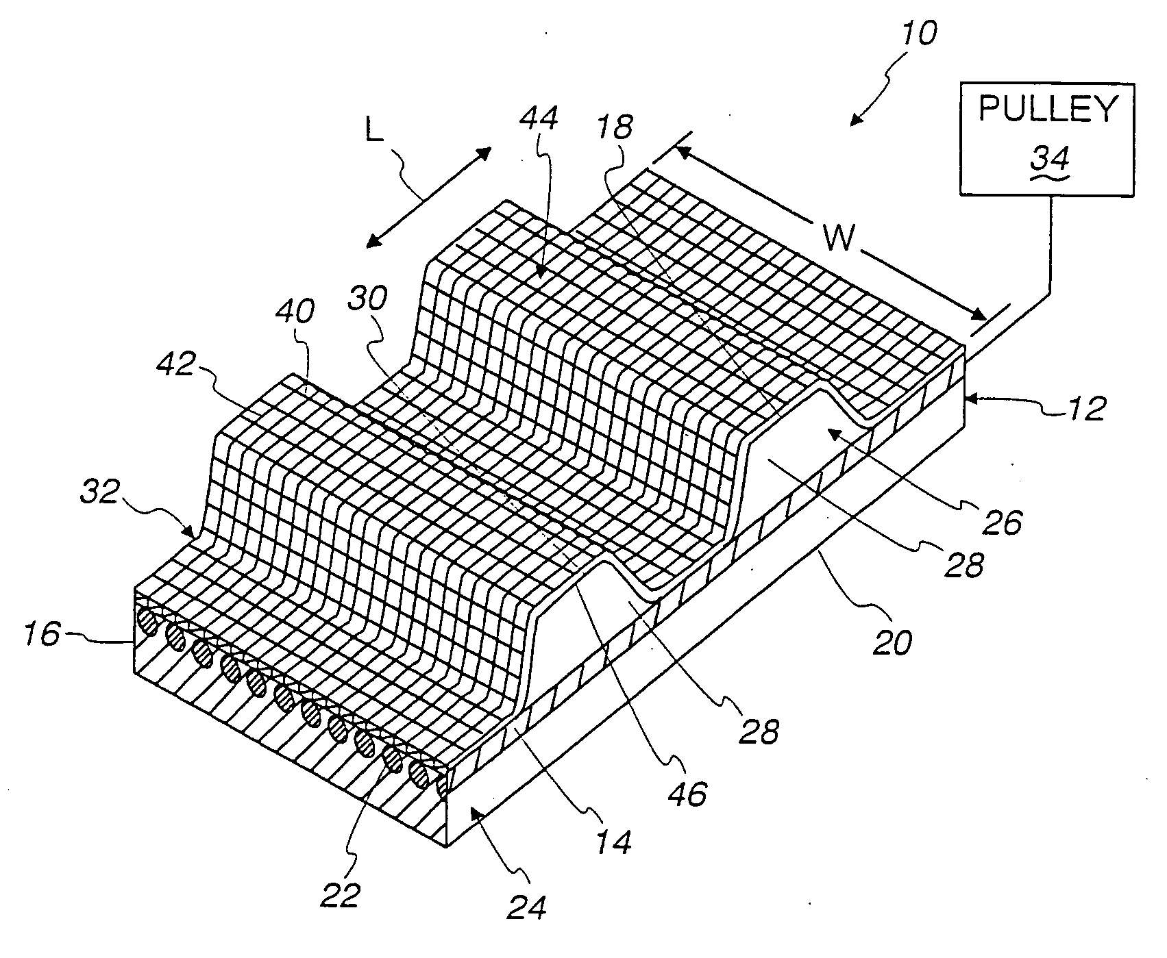
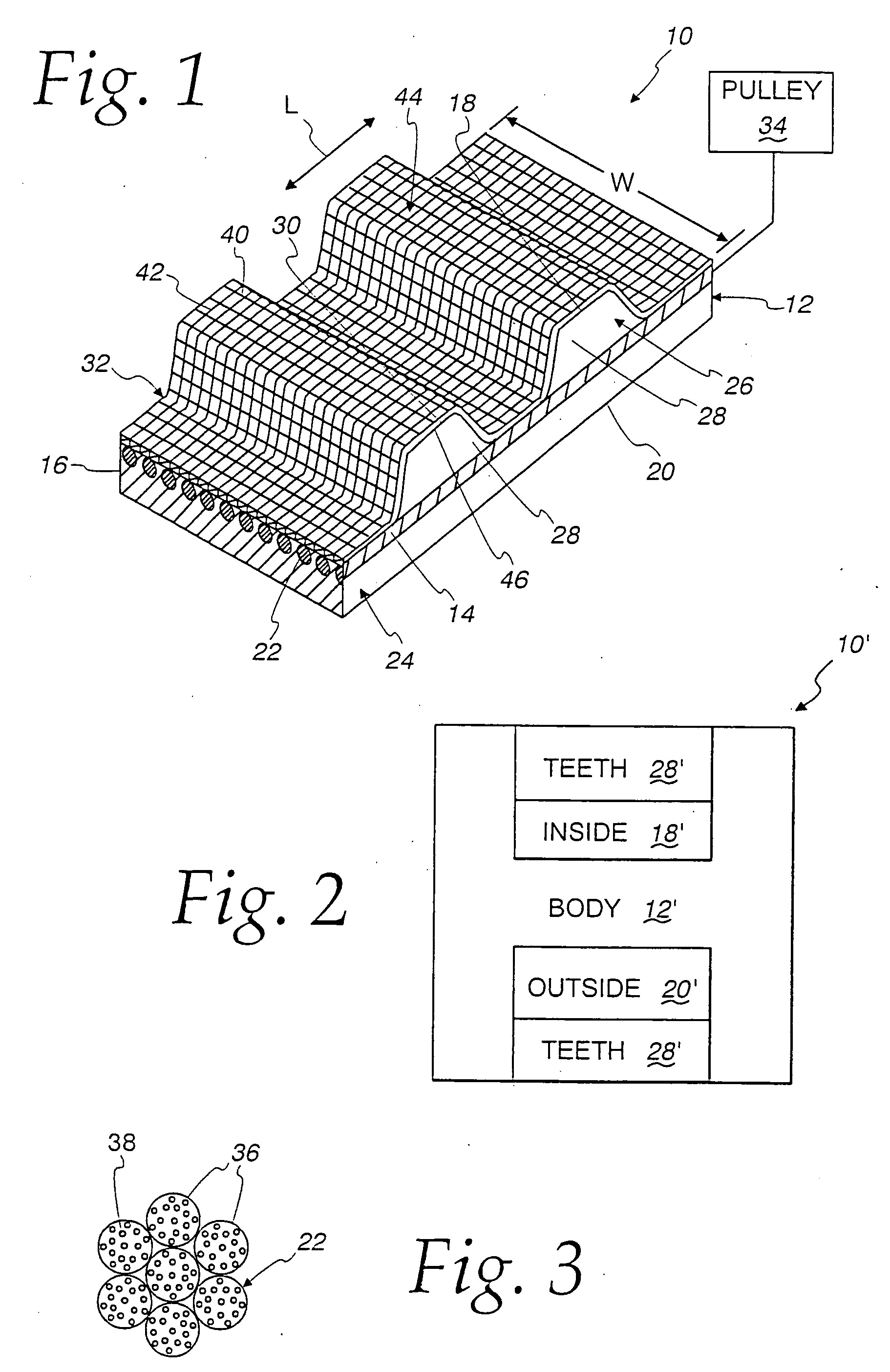
[0046]In FIG. 1, a toothed power transmission belt, made according to the present invention, is shown at 10. The power transmission belt 10 has a body 12 with a length, extending in the direction of the double-headed arrow L, and width W, between laterally spaced sides 14, 16. The body 12 has an inside 18 and an outside 20. The designations “inside” and “outside” are arbitrary as they could be reversed.

[0047]The body 12 is made from a rubber composition and includes at least one embedded load carrying member 22 extending in a lengthwise direction. The load carrying member(s) 22 may be a spirally wrapped single component or a plurality of components spaced laterally from each other. For purposes of explanation herein, the load carrying members 22 will be considered to be plural members, whether made from a single component with spaced turns or multiple, separate, laterally spaced components.

[0048]The belt body 12 is made with two different sections—a back section 24 in which the load...


PUM

PropertyMeasurementUnit
angleaaaaaaaaaa
lengthaaaaaaaaaa
widthaaaaaaaaaa

Abstract

A power transmission belt having a body with a length, a width between laterally spaced sides, and a thickness between inside and outside surfaces. At least one load carrying member extends in a lengthwise direction. The body has a plurality of teeth spaced along at least one of the inside and outside of the body. The teeth have a width that decreases progressively from: a) a first location between the inside and outside surfaces; and b) one of the inside and outside surfaces so that the one surface has a width that is less than a width of the other surfaces. A cloth layer is applied to the one surface and is a multiwoven structure with interwoven: a) warp; and b) at least two different wefts.

Description

CROSS-REFERENCE TO RELATED APPLICATIONS[0001]This application is a continuation-in-part of application Ser. No. 12 / 214,690 filed Jun. 20, 2008.BACKGROUND OF THE INVENTION[0002]1. Field of the Invention[0003]This invention relates to power transmission belts and, more particularly, to a power transmission belt with pulley engaging teeth spaced along the length of the belt.[0004]2. Background Art[0005]It is known to make power transmission belts from rubber with teeth spaced at regular intervals along the length of the belt. These belts are commonly used in high load applications, as in association with engines and other driving / driven devices. It is also known to incorporate and embed in these belts load carrying members, that extend lengthwise of the belt. A cloth layer is commonly placed over a surface of the belt upon which the teeth are formed. Exemplary of such a construction is that shown in Gazette of Japanese Patent Laid-Open 2002 / 168,302.[0006]In this type of toothed belt, h...

Claims


Application Information

Patent Timeline
Patent Type & Authority Applications(United States)
IPC IPC(8): F16G1/10F16G1/06F16H7/02
CPCF16G1/28
Inventor IZU, YASUYUKIYOSHIDA, MASAKUNIOKABE, HIROFUMI
Owner MITSUBOSHI BELTING LTD
Why Eureka
Try Eureka