System and method for determining appropriate steering tables for distributing stimulation energy among multiple neurostimulation electrodes

a neurostimulation electrode and steering table technology, applied in electrotherapy, therapy, etc., can solve the problems of not being able to effectively steer current in a side-by-side lead configuration, affecting and frustrating the patient and the physician/clinician to the point of steering

Inactive Publication Date: 2010-05-13
BOSTON SCI NEUROMODULATION CORP
View PDF7 Cites 342 Cited by
  • Summary
  • Abstract
  • Description
  • Claims
  • Application Information

AI Technical Summary

Benefits of technology

[0022]In accordance with a first aspect of the present inventions, a method of programming a control device is provided. The control device is configured for controlling electrical stimulation energy provided to a plurality of electrode leads that are physically implanted within a patient (e.g., adja...

Problems solved by technology

However, the number of electrodes available, combined with the ability to generate a variety of complex stimulation pulses, presents a huge selection of stimulation parameter sets to the clinician or patient.
Thus, correct lead placement can mean the difference between effective and ineffective pain therapy.
Notably, a navigation table that was specifically designed to provide current steering for a side-by-side lead configuration that would result in the sharing of current between the electrodes of the respective leads could not be effectively used to steer current in an in-line lead configuration designed to separately treat different pain regions—else the navigation table would result in confusing, possibly simultaneous stimulation.
Likewise, a navigation table that was specifically designed to provide current steering for an in-line lead configurati...

Method used


Image

  • System and method for determining appropriate steering tables for distributing stimulation energy among multiple neurostimulation electrodes
  • System and method for determining appropriate steering tables for distributing stimulation energy among multiple neurostimulation electrodes
  • System and method for determining appropriate steering tables for distributing stimulation energy among multiple neurostimulation electrodes

Examples


Embodiment Construction

[0071]The description that follows relates to a spinal cord stimulation (SCS) system. However, it is to be understood that the while the invention lends itself well to applications in SCS, the invention, in its broadest aspects, may not be so limited. Rather, the invention may be used with any type of implantable electrical circuitry used to stimulate tissue. For example, the present invention may be used as part of a pacemaker, a defibrillator, a cochlear stimulator, a retinal stimulator, a stimulator configured to produce coordinated limb movement, a cortical stimulator, a deep brain stimulator, peripheral nerve stimulator, microstimulator, or in any other neural stimulator configured to treat urinary incontinence, sleep apnea, shoulder sublaxation, headache, etc.

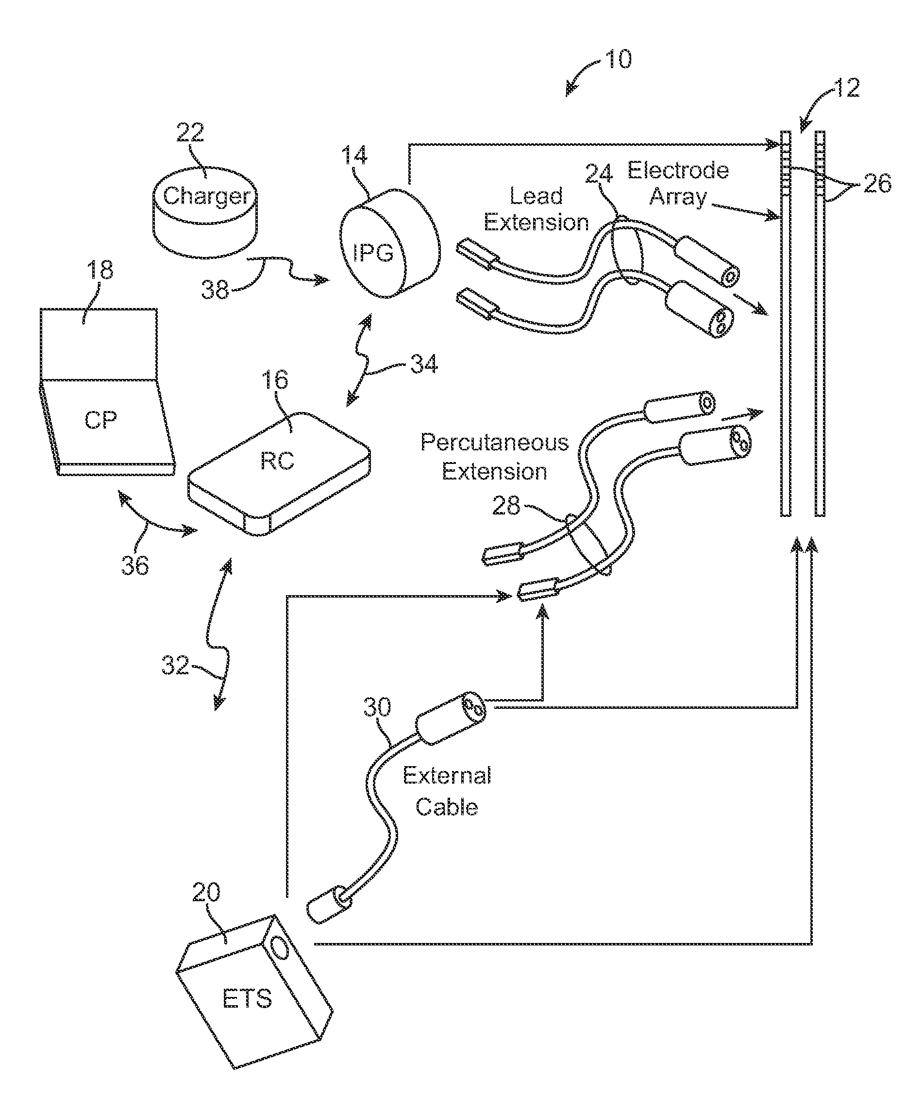
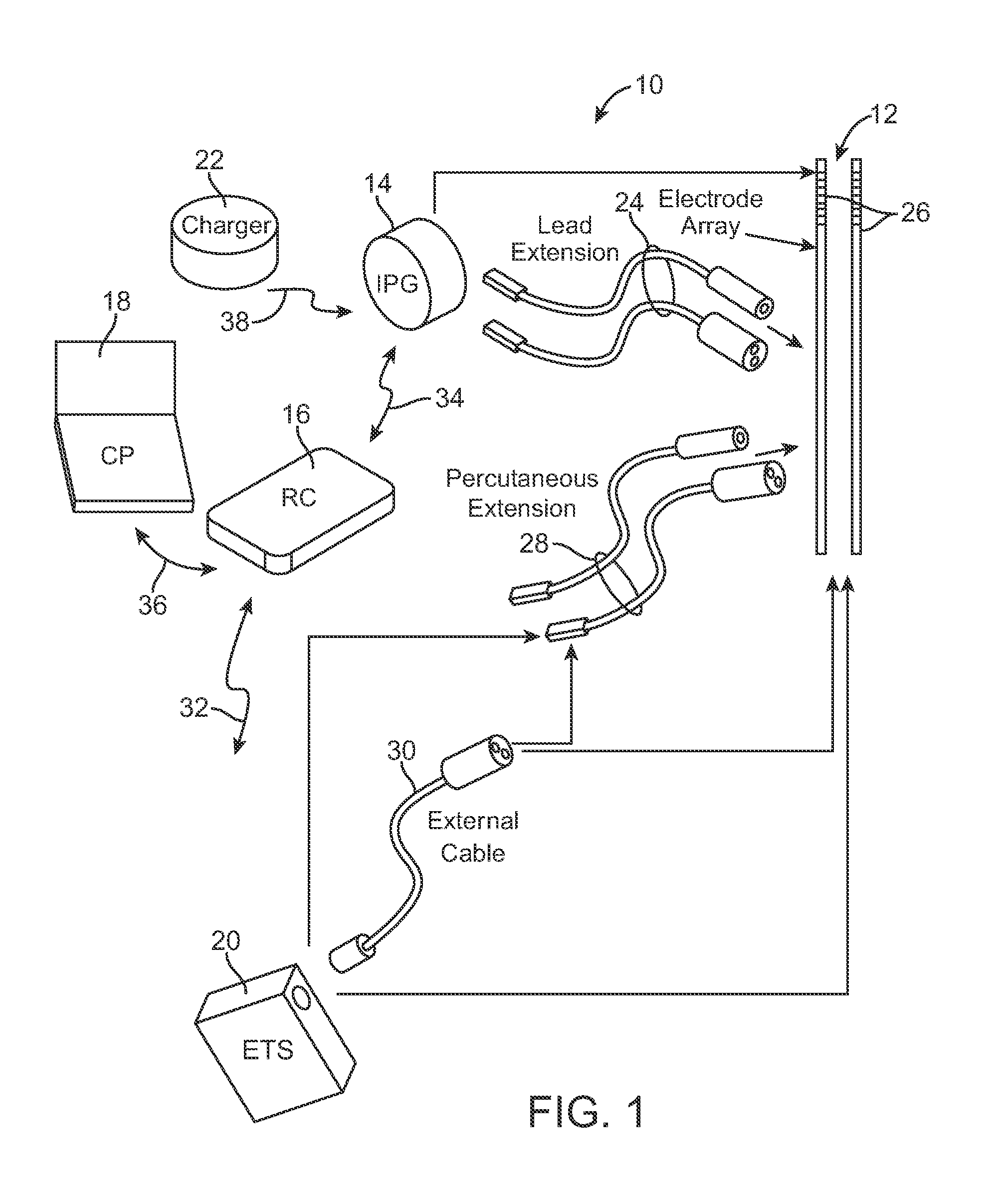
[0072]Turning first to FIG. 1, an exemplary SCS system 10 generally includes a plurality (in this case, two) of implantable stimulation leads 12, an implantable pulse generator (IPG) 14, an external remote controller RC 1...


PUM


Abstract

A method, computer medium, and system for programming a control device are provided. The control device is configured for controlling electrical stimulation energy provided to a plurality of electrode leads that are physically implanted within a patient in a side-by-side lead configuration. Electrical energy is conveying from the electrode leads to create a stimulation region within the patient. The stimulation region is automatically shifted along the electrode leads (e.g., by selecting and using at least one navigation table) in accordance with an electrical current shifting pattern that is based on a stagger of the side-by-side lead configuration. At least one stimulation parameter set is selected based on the effectiveness of the shifted stimulation region, and the control device is programmed with the selected stimulation parameter set(s).

Description

RELATED APPLICATION[0001]The present application claims the benefit under 35 U.S.C. §119 to U.S. provisional patent application Ser. No. 61 / 113,973, filed Nov. 12, 2008. The foregoing application is hereby incorporated by reference into the present application in its entirety.FIELD OF THE INVENTION[0002]The present invention relates to tissue stimulation systems, and more particularly, to a system and method for programming an implantable tissue stimulator.BACKGROUND OF THE INVENTION[0003]Spinal cord stimulation (SCS) is a well-accepted clinical method for reducing pain in certain populations of patients. Spinal cord stimulator and other implantable tissue stimulator systems come in two general types: radio-frequency (RF)-controlled and fully implanted. The type commonly referred to as an “RF” system includes an external RF transmitter inductively coupled via an electromagnetic link to an implanted receiver-stimulator connected to one or more leads with one or more electrodes for st...

Claims


Application Information

Patent Timeline
IPC IPC(8): A61N1/08
CPCA61N1/37247A61N1/36185A61N1/36157A61N1/36071A61N1/37264
Inventor KOTHANDARAMAN, SRIDHARWOODS, CARLA MANNBRADLEY, KERRYTHACKER, JAMES R.KARNATI, SIVAKUMAR
Owner BOSTON SCI NEUROMODULATION CORP
Why Eureka
Try Eureka