Stent delivery system

a delivery system and stent technology, applied in the field of stent delivery system, can solve the problems of inability to effectively dilate the stricture site, increased uniformity, and increased risk of stent fall off, and achieves the effect of preventing fall off, superior trackability performance, and easy production

Inactive Publication Date: 2010-05-13
KANEKA CORP
View PDF4 Cites 43 Cited by
  • Summary
  • Abstract
  • Description
  • Claims
  • Application Information

AI Technical Summary

Benefits of technology

[0022]The present invention provides a stent delivery system that is superior in trackability performance and that can be produced easily without any complicated steps because a retention mechanism for prevention of fall-off of the stent is formed when a force moving the stent in the catheter axial direction is applied and the crimped stent is simply placed on the folded balloon when the force is not applied.

Problems solved by technology

However, the stent-retention force applied from outside is not sufficient for fixation of the stent therein, and thus there was a concern about the stent being caught in a bent region of vascular system such as blood vessel, and thus the stent being dislocated or removed from its original site on balloon catheter by the frictional resistance during insertion, for example by friction between the hemostasis valve and the guide catheter or friction in meandering vascular system.
The stent, if dislocated from its original site, cannot be expanded uniformly and thus, cannot dilate the stricture site effectively.
The stent, if it falls off, is dangerous because it possibly remains in the body.
However, it is difficult by the method to form the projections on the external and internal surfaces of the balloon, and there is a concern that capturing and embedding of the complicatedly shaped stent by the projections may be unstable.
The increase in crimping profile leads to expansion of the diameter of the shaft in the catheter distal end region and deterioration in flexibility of the region.
There is a concern in the method that the sleeve formed on the catheter may lead to increase in profile and also in production man-power.
It is also difficult to place the stent in the folded balloon.
The increase in profile leads to deterioration in flexibility, causing problems such as deterioration in trackability performance due to increase in passage resistance in blood vessel and increase in complexity of the steps for installing the mechanism, and increase in man power for the production steps.

Method used


Image

  • Stent delivery system
  • Stent delivery system
  • Stent delivery system

Examples


example 1

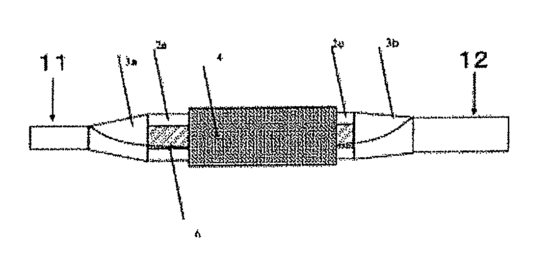
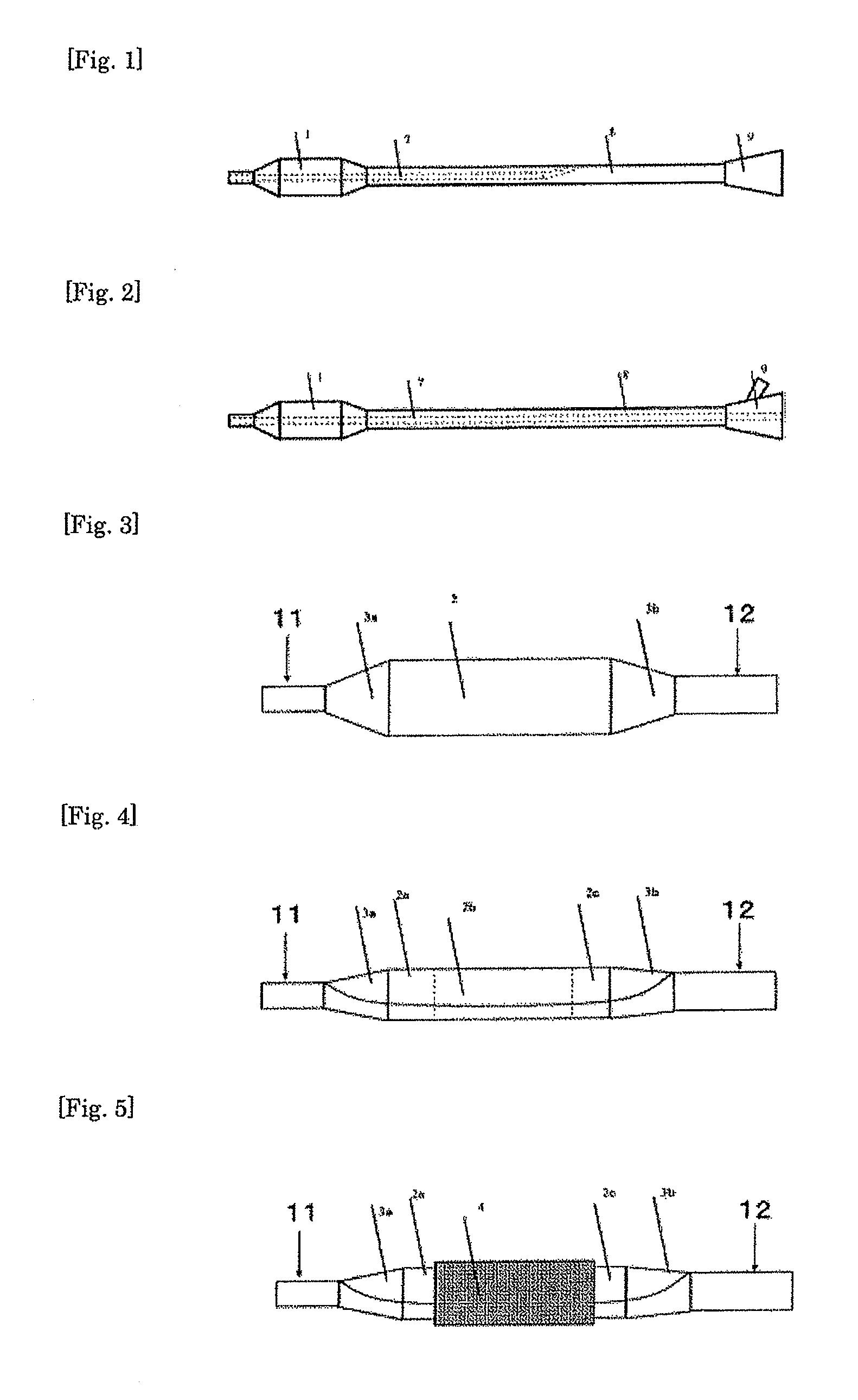
[0085]A catheter was prepared according to the procedure described below. The entire structures of the catheter of Example 1 and its explanation are the same as those exemplified in FIGS. 1 and 3 and described above in the embodiments.

[0086]A tubular parison (internal diameter: 0.45 mm, external diameter: 0.87 mm) was prepared with a polyamide elastomer (trade name: PEBAX7233SA01; manufactured by Elf Atochem) by extrusion molding; and a balloon having a straight-tube region, with an external diameter of 3.00 mm, a length of 20.5 mm, and a taper angle of 50°, having thickness 16 μm at around the center, a distal end-sided tapered region having a thickness of 19 μm at around the center, and a proximal end-sided tapered region having a thickness of 19 μm at around the center was then prepared with the parison by biaxial-stretching blow molding. The thicknesses of the distal end-sided tapered region, the straight-tube region, and the proximal end-sided tapered region respectively at aro...


PUM

PropertyMeasurementUnit
external forceaaaaaaaaaa
taper angleaaaaaaaaaa

Abstract

A stent delivery system comprises a delivery catheter with a balloon and a stent. The stent delivery system is characterized in that when a force to move the stent in the axial direction of the catheter is applied to the stent, a holding mechanism is formed in a part of the balloon to prevent the stent from falling down. According to this invention, the stent delivery system that is capable of preventing the stent from falling down and has excellent track ability can be provided without requiring complicated manufacturing processes.

Description

TECHNICAL FIELD[0001]The present invention relates to a stent delivery system including a delivery catheter having a balloon and a stent.BACKGROUND ART[0002]Stents have been used widely for dilation of stricture sites formed in vascular systems in human body, and assuring the preservation of the routes. A stent is placed in a catheter called delivery catheter as it is folded and inserted into and expanded in the body.[0003]There are two kinds of stents according to the expanding mode. One is a balloon-expandable stent that is expanded by expansion force applied by a balloon expanded with a pressurized fluid by a balloon catheter. The other is a self-expandable stent that expands by itself, for example as it is made of a shape-memory alloy.[0004]In the case of the balloon-expandable stent, the stent is folded and tightened around a shaft before installation into a delivery catheter. However, the stent-retention force applied from outside is not sufficient for fixation of the stent th...

Claims


Application Information

Patent Timeline
Patent Type & Authority Applications(United States)
IPC IPC(8): A61F2/84A61F2/958
CPCA61F2/958A61F2002/9583A61M2025/0046
Inventor SHIMADA, TAMOTSU
Owner KANEKA CORP
Why Eureka
Try Eureka