Apparatus and method for identifying the absolute rotation of a rotating imaging system

an imaging system and absolute rotation technology, applied in the field of imaging systems, can solve the problems of not being able to easily stop rotation at a position, operator may not know if the retractor is nearing the end of its travel, and cannot stop the heavy modern imaging detector safely

Active Publication Date: 2010-05-13
GENERAL ELECTRIC CO
View PDF19 Cites 19 Cited by
  • Summary
  • Abstract
  • Description
  • Claims
  • Application Information

AI Technical Summary

Benefits of technology

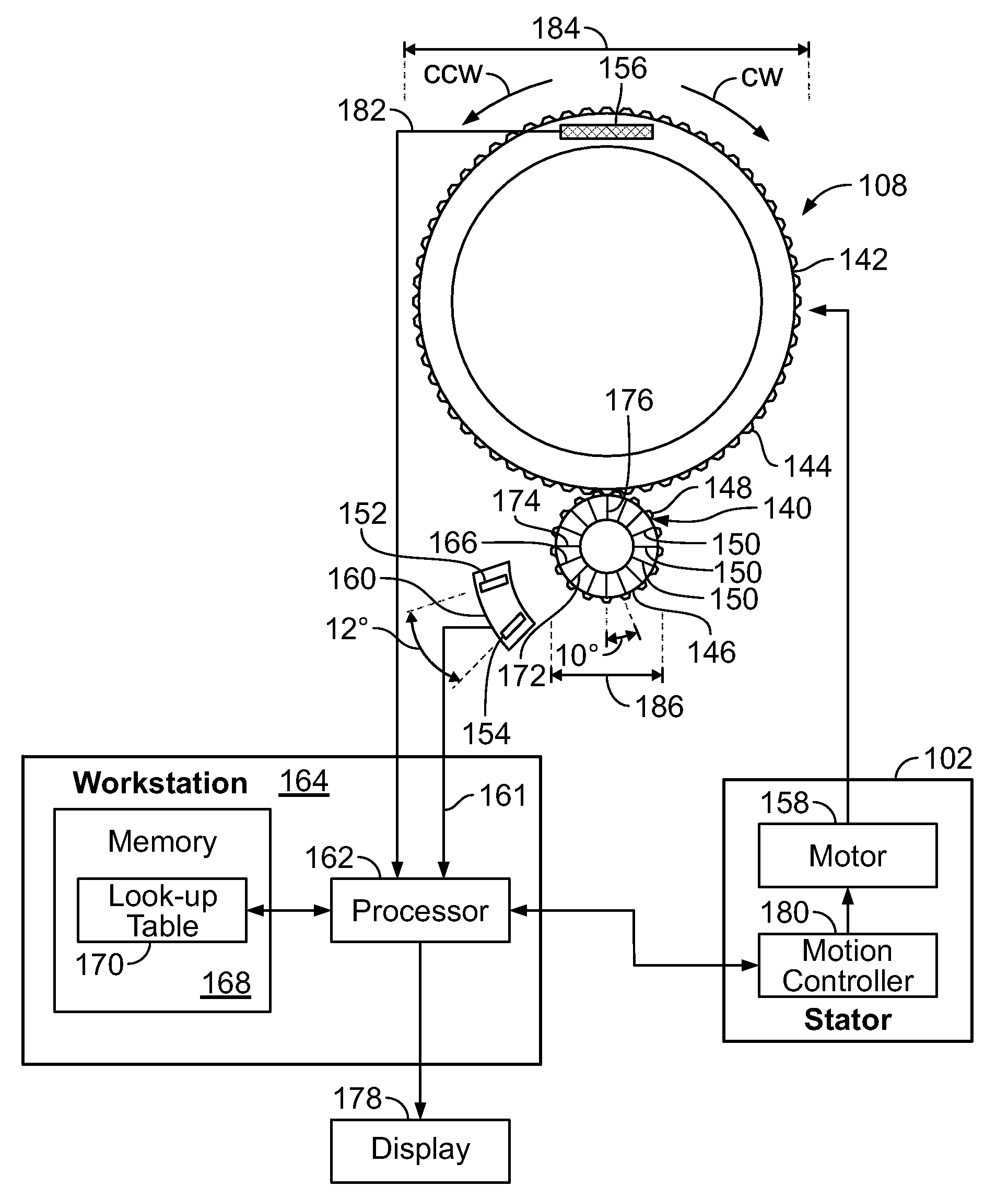
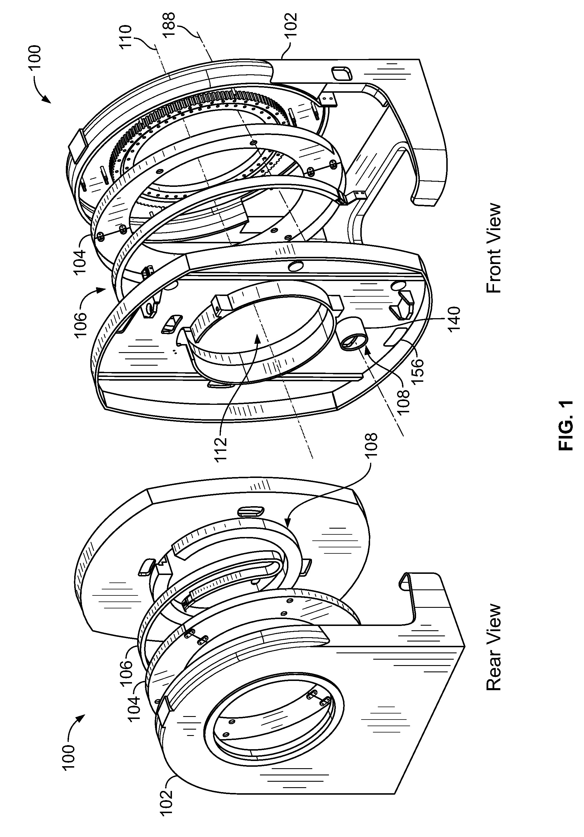
[0004]In one embodiment, a rotating imaging system has a rotating portion, an idler, at least one sensor, a tilt sensor and a processor. The rotating portion has a diameter and is configured to rotate about a central axis. The idler is configured to rotate about an axis parallel to the central axis, and has a second diameter that is smaller than the diameter of the rotating portion. The rotating portion and the idler are configured to engage with each other such that both rotate simultaneously. The at least one sensor is configured to detect flags on the idler as the idler rotates. The tilt sensor is mounted to the rotating portion and is configured to determine a rotation angle of the rotating portion within a range of one revolution, and the processor is configured to determine an absolute rotation of the rotating portion based on at least a signal from the at least one sensor and the rotation angle determined by the tilt sensor.

Problems solved by technology

Mechanical devices such as hard stops have been used, but cannot safely stop heavy modern imaging detectors and may not be easily positioned to stop rotation at a position less than two full revolutions.
If the tracking or corresponding display fails, such as during a power outage or computer or other component malfunction, an operator may not know if the retractor is nearing the end of travel.
Moving the rotating portion beyond the end of travel, such as manually or by driving with a motor, may cause severe damage to the system.
Specifically, the retractor may be damaged if the rotating portion travels beyond the designed travel limit.

Method used


Image

  • Apparatus and method for identifying the absolute rotation of a rotating imaging system
  • Apparatus and method for identifying the absolute rotation of a rotating imaging system
  • Apparatus and method for identifying the absolute rotation of a rotating imaging system

Examples


Embodiment Construction

[0018]The foregoing summary, as well as the following detailed description of certain embodiments of the present invention, will be better understood when read in conjunction with the appended drawings. To the extent that the figures illustrate diagrams of the functional blocks of various embodiments, the functional blocks are not necessarily indicative of the division between hardware circuitry. Thus, for example, one or more of the functional blocks (e.g., processors or memories) may be implemented in a single piece of hardware (e.g., a general purpose signal processor or random access memory, hard disk, or the like). Similarly, the programs may be stand alone programs, may be incorporated as subroutines in an operating system, may be functions in an installed software package, and the like. It should be understood that the various embodiments are not limited to the arrangements and instrumentality shown in the drawings.

[0019]As used herein, an element or step recited in the singu...


PUM


Abstract

A rotating imaging system has a rotating portion, an idler, at least one sensor, a tilt sensor and a processor. The rotating portion has a diameter and rotates about a central axis. The idler rotates about an axis parallel to the central axis, and has a second diameter that is smaller than the diameter of the rotating portion. The rotating portion and the idler engage with each other such that both rotate simultaneously. The at least one sensor detects flags on the idler as the idler rotates. The tilt sensor is mounted to the rotating portion and determines a rotation angle of the rotating portion within a range of one revolution, and the processor determines an absolute rotation of the rotating portion based on at least a signal from the at least one sensor and the rotation angle determined by the tilt sensor.

Description

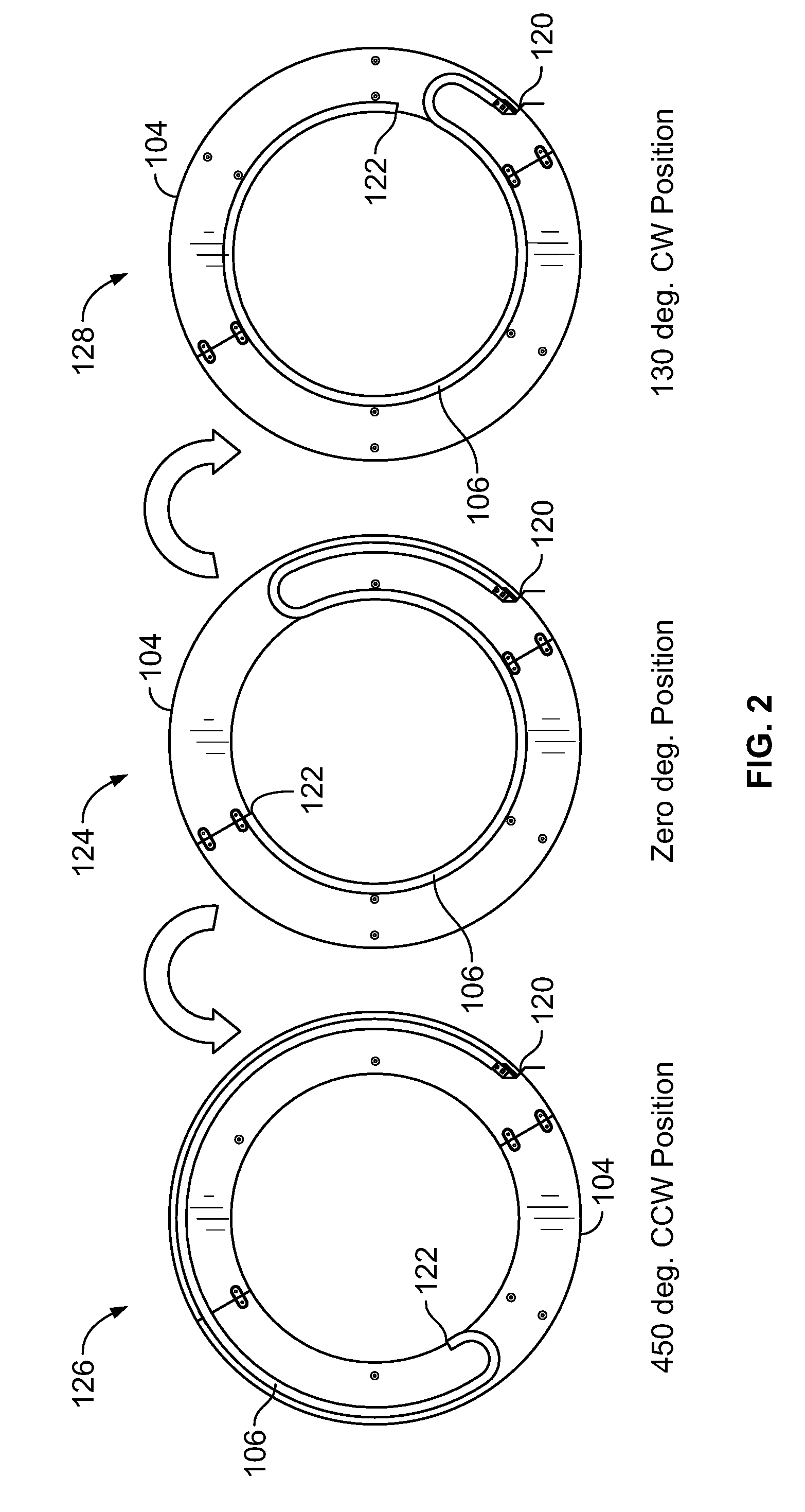
BACKGROUND OF THE INVENTION[0001]This invention relates generally to imaging systems, and more particularly to imaging systems that use a retractor.[0002]Some imaging systems such as nuclear medicine imaging systems having gamma cameras use a retractor as a transmission system to transmit power, signals and data between the imaging detectors and electronics used for processing, control and power. The retractor may also be referred to as a cable guidance system and allows a limited rotation span. For example, the rotor or rotating portion upon which the imaging detectors are mounted typically may be rotated more than one, but less than two full rotations in one or both of the clockwise (CW) and counter-clockwise (CCW) directions from a zero position. In contrast, a slip ring, such as those used by computed tomography (CT) and some gamma camera systems, allow unlimited rotations in both the CW and CCW directions.[0003]Electronics track the rotating portion during normal use, such as b...

Claims


Application Information

Patent Timeline
Patent Type & Authority Applications(United States)
IPC IPC(8): G01C9/00G08B21/00
CPCA61B6/032G01C9/00A61B6/56A61B6/547
Inventor VAISBURD, ALEXANDERYAKUBOVSKY, LEONID
Owner GENERAL ELECTRIC CO
Why Eureka
Try Eureka