Method for forming an isolated inner lead from a leadframe

a leadframe and inner lead technology, applied in the field of leadframe manufacturing, can solve the problems of increasing the risk of exposing the bonding wire from the encapsulant, increasing the thickness of the package, and complicated packaging processes, so as to avoid the height difference and displacement of the wire bonding

Active Publication Date: 2010-05-20
POWERTECH TECHNOLOGY
View PDF1 Cites 8 Cited by
  • Summary
  • Abstract
  • Description
  • Claims
  • Application Information

AI Technical Summary

Benefits of technology

[0004]The main purpose of the present invention is to provide a method for forming an isolated inner lead from a leadframe where the isolated inner leads are electrically isolated from the leads of a leadframe for completely encapsulating in an encapsulant to achieve redistribution of pin assignments and electrical paths without disposing extra internal redistributing components for wire bonding and to avoid wire-bonding height differences and displacement at non-chip bonding points.
[0007]The method for forming an isolated inner lead from a leadframe revealed according to the present invention has the following advantages and functions:
[0008]1. The leadframe having the isolated inner lead can achieve redistribution of pin assignments and electrical paths with the isolated inner lead and the inner portions of normal leads located inside the molding area in the same metal layer, and with the arrangements of leads, and with the disposition of a plurality of insulating tapes without disposing extra internal redistributing components for wire bonding and to avoid wire-bonding height differences and displacement at non-chip bonding points. Furthermore, the isolated inner lead is electrically isolated and mechanically fixed in the molding area.

Problems solved by technology

However, there are extra costs to deposit a second leadframe or internal redistributing components on specific locations so that the packaging processes become more complicated with higher risks of exposing bonding wires from the encapsulant where package thickness is also increased.
Moreover, the non-chip bonding ends of bonding wires will cause wire bonding height differences and displacement leading to constant adjusting of wire bonding parameters.

Method used


Image

  • Method for forming an isolated inner lead from a leadframe
  • Method for forming an isolated inner lead from a leadframe
  • Method for forming an isolated inner lead from a leadframe

Examples


first embodiment

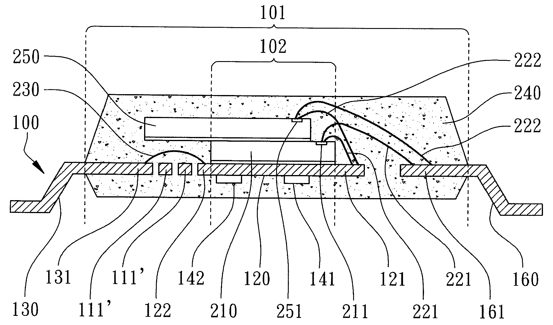
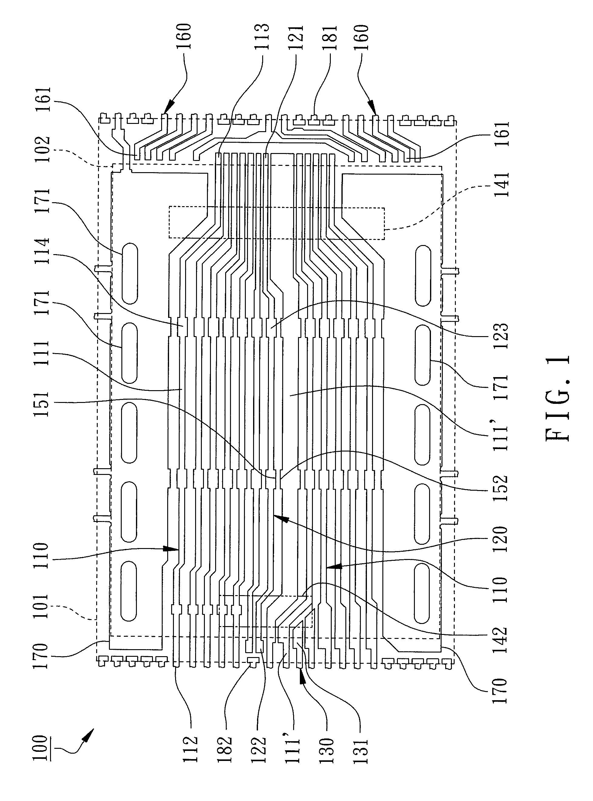
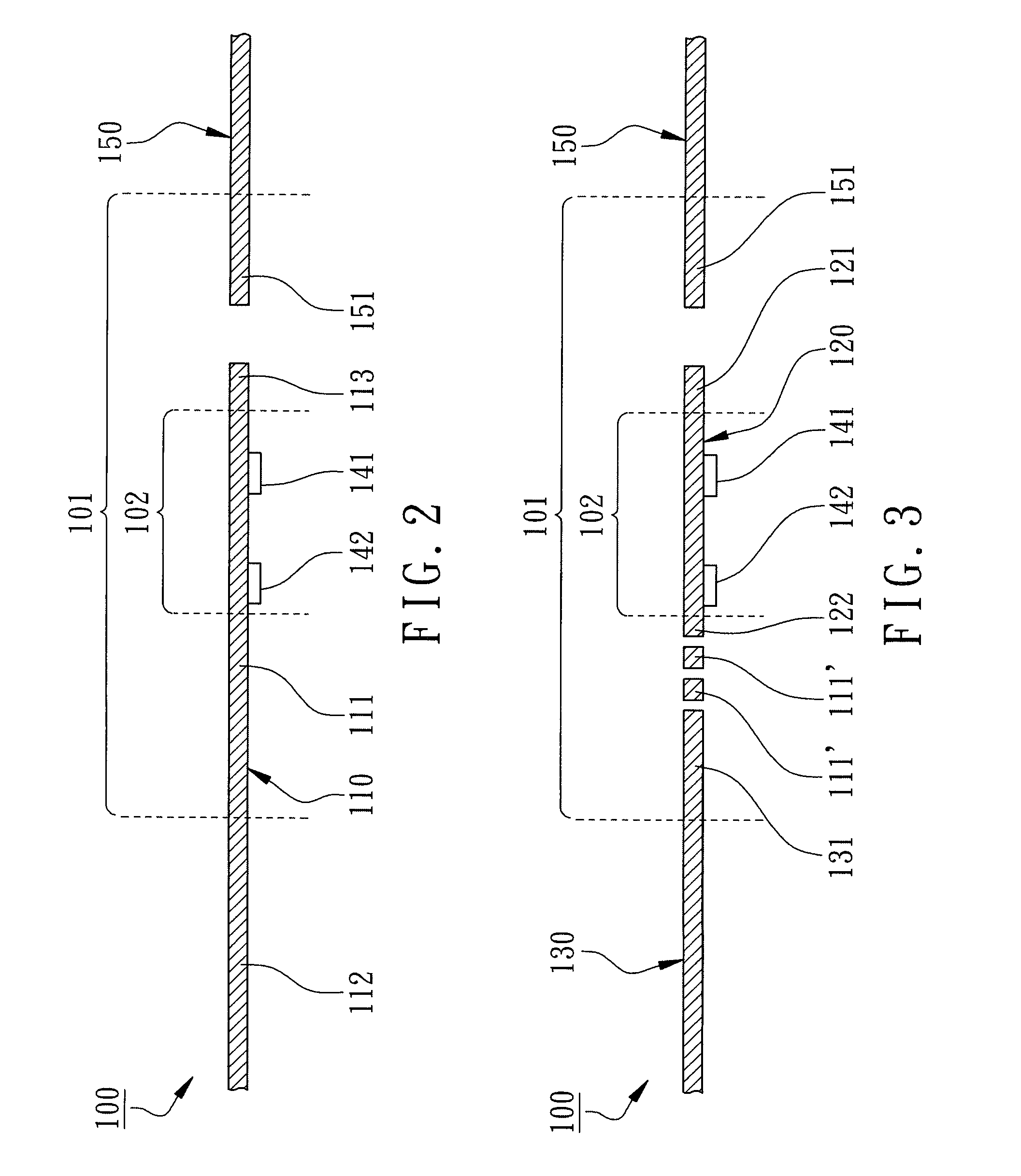
[0019]According to the present invention, the method for forming an isolated inner lead from a leadframe is disclosed. The leadframe having isolated inner leads formed from the method is illustrated in FIG. 2 for a partial top view. A molding area 101 and a die-attaching area 102 are defined in the leadframe 100 where the die-attaching area 102 is disposed inside the molding area 101 corresponding to the footprint of an attached chip 210, as shown in FIG. 6, and the molding area 101 is an area corresponding to an encapsulant 240. The dimension of the molding area 101 is greater than the one of the die-attaching area 102 so that the encapsulant 240 can fully encapsulate the chip 210 or more chips. The leadframe 100 is a patterned metal sheet including a plurality of leads 110, at least an isolated inner lead 120 and at least an external lead 130. A first insulating tape 141 and a second insulating tape 142 are attached to the leadframe 100 for mechanically connecting the isolated inn...

second embodiment

[0032]According to the present invention, another leadframe having isolated inner leads is illustrated in FIG. 7 for a partial top view and in FIG. 8 for a partial top view before disposing the insulating tapes. A molding area 101 and a die-attaching area 102 disposed inside the molding area 101 are defined on the leadframe 100 where the leadframe 100 comprises a plurality of leads 110, an isolated inner lead 120 and an external lead 130. A first insulating tape 141 and a second insulating tape 142 are attached to the leadframe 100.

[0033]Each lead 110 has an inner portion 111 located inside the molding area 101 and an external portion 112 extended outside the molding area 101 where the inner portion 111 and the external portion 112 are integrally connected to each other. A first bonding finger 113 is formed on the inner end of each inner portion 111. The isolated inner lead 120 is completely located inside the molding area 101 and is formed from the same layer of the leadframe with ...


PUM

PropertyMeasurementUnit
areaaaaaaaaaaa
insulatingaaaaaaaaaa
lengthaaaaaaaaaa

Abstract

A method for forming an isolated inner lead from a leadframe is revealed. The leadframe primarily comprises a plurality of leads, the isolated inner lead, and an external lead. Each lead has an inner portion having a finger. The isolated inner lead having two fingers is completely formed inside a molding area and is made of the same metal leadframe as the leads. One finger of the isolated inner lead and the fingers of the leads are linearly arranged. The other finger of the isolated inner lead is adjacent to a finger of the external lead. At least one of the inner portions divides the isolated inner lead from the external lead. The isolated inner lead is integrally connected to an adjacent one of the inner portions by a connecting block. A tape-attaching step is performed to mechanically connect the isolated inner lead where two insulating tapes are attached in a manner that the connecting block can be removed. Therefore, the isolated inner lead is electrically isolated from the leads and can be mechanically fixed to replace extra redistributing components during semiconductor packaging processes.

Description

FIELD OF THE INVENTION[0001]The present invention relates generally to manufacturing a leadframe for semiconductor packages, especially to a method for forming an isolated inner lead from a leadframe.BACKGROUND OF THE INVENTION[0002]Leadframes used in semiconductor packages as chip carriers are patterned metal sheets including a plurality of metal leads, which have the advantages of lower packaging costs where chips are attached on leadframes and then are encapsulated by encapsulants. The semiconductor packages are mounted to external printed circuit boards through the external portions of the leads of leadframes. In order to form encapsulants by molding, the leads of leadframe are extended outside the molding area to be clamped by top and bottom mold tools. Moreover, leadframes are normally made by either etching or punching a metal sheet to form a plurality of leads.[0003]Since the leads are formed from the same layer of a leadframe, the sequence of the leads is fixed and can not ...

Claims


Application Information

Patent Timeline
Patent Type & Authority Applications(United States)
IPC IPC(8): H01R43/00
CPCH01L2224/4911H01L23/49558Y10T29/49121H01L2224/32245H01L2225/06562H01L2924/19107H01L23/4951H01L2224/32145H01L2924/01029H01L2924/01082H01L23/49575H01L2224/48257H01L2224/73265H01L24/48H01L2224/48091H01L2224/48247H01L24/49H01L2924/01033H01L2924/00014H01L2924/00H01L2924/181H01L2924/35121H01L2224/45099H01L2224/05599H01L2924/00012
Inventor FAN, WEN-JENGHSU, YU-MEI
Owner POWERTECH TECHNOLOGY
Why Eureka
Try Eureka