Reactor and method of producing the reactor

a reactor and reactor technology, applied in the direction of transformer/inductance magnetic cores, magnets, magnetic bodies, etc., can solve the problems of generating cracks in the reactor, core breaks, conventional reactors have a following drawback, etc., to reduce stress, reduce the elastic modulus of the entire core, and reduce the stress

Active Publication Date: 2010-05-20
DENSO CORP +1
View PDF7 Cites 10 Cited by
  • Summary
  • Abstract
  • Description
  • Claims
  • Application Information

AI Technical Summary

Benefits of technology

[0013]Using the non-magnetic powder composed of the low elastic modulus powder in addition to the main component powder in the core of the reactor can decrease the elastic modulus of the entire non-magnetic powder, and further decrease the elastic modulus of the entire core. This structure allows decreasing of the stress applied from the coil to the core in the reactor when a current flows in the coil. As a result, it is possible to provide the reactor capable of suppressing the core from damaging and breaking.
[0014]Further, the above structure of the reactor according to the present invention can decrease the elastic modulus of the entire core without decreasing the content of the magnetic powder in the core. It is thereby possible to maintain the magnetic characteristics of the reactor while suppressing the core from damaging and breaking.
[0015]Still further, because the non-magnetic powder contains the main component powder having a heat conductivity which is larger than that of the resin, it is possible for the reactor to adequately radiate heat energy. This can maintain the magnetic characteristics and radiation performance of the reactor.
[0016]As described above, according to the present invention, it is possible to provide the reactor capable of suppressing the core from damaging and breaking while maintaining the magnetic characteristics thereof.
[0018]The method according to the present invention provides the reactor capable of decreasing the elastic modulus of the entire non-magnetic powder without decreasing the content of the magnetic powder contained in the core. As a result, the method provides the reactor capable of adequately decreasing the elastic modulus of the entire core. It is thereby possible to decrease the stress to be applied to the core from the coil when the coil is thermally expanded during a current flowing in the coil. In other words, the method according to the present invention can produce the reactor capable of suppressing the core from damaging and breaking while maintaining the magnetic characteristics of the entire reactor.

Problems solved by technology

However, the conventional reactor has a following drawback.
This often causes that the core breaks, and a crack is generated in the reactor.
This makes it impossible to provide a predetermined magnitude of inductance of the reactor.
In general, a high elastic modulus of the core often causes a crack therein.
However, this can decrease the magnetic characteristics of the core, and thereby makes it difficult to generate a desired amount of magnetic flux.

Method used


Image

  • Reactor and method of producing the reactor
  • Reactor and method of producing the reactor
  • Reactor and method of producing the reactor

Examples


first embodiment

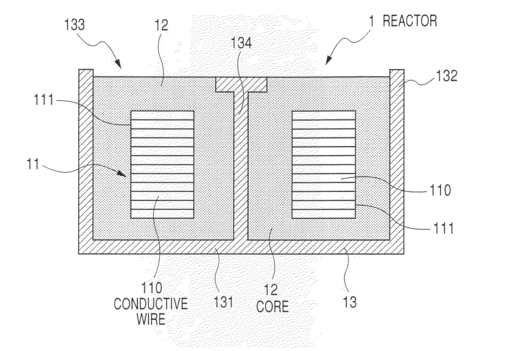
[0030]A description will be given of a reactor according to a first embodiment of the present invention with reference to FIG. 1 to FIG. 4A, FIG. 4B, and FIG. 4C, and FIG. 7.

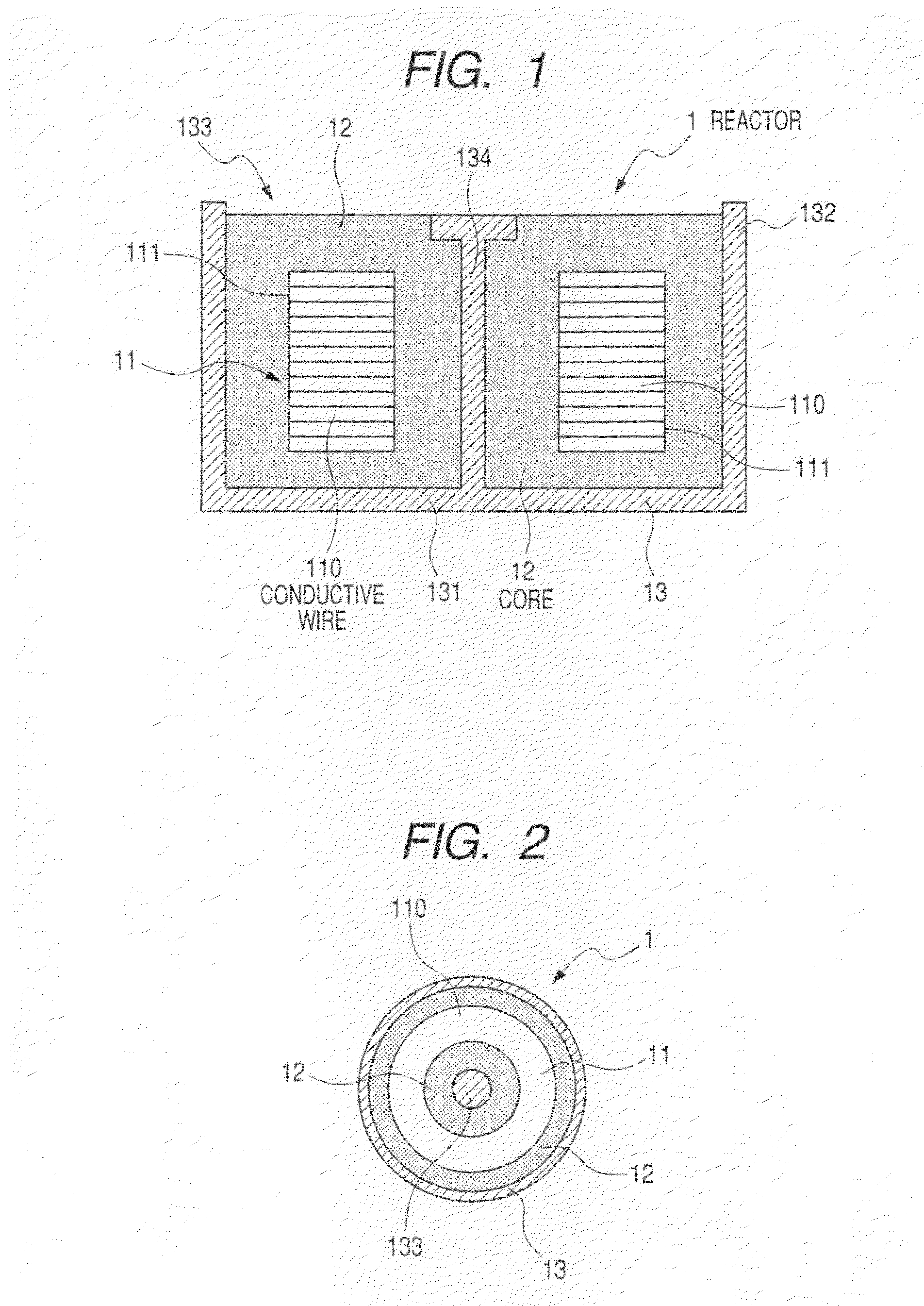
[0031]FIG. 1 is a vertical cross-sectional view showing the reactor 1 according to the first embodiment of the present invention. FIG. 2 is a top view of the reactor 1 according to the first embodiment shown in FIG. 1.

[0032]As shown in FIG. 1 and FIG. 2, the reactor 1 is comprised of a coil 11 and a core 12. The coil 11 is made by winding a flat type conductive wire 110. The coil 11 generates magnetic flux when a current flows therein. The core 12 is placed in an inside area and an outside area of the coil 11 in a container (or a case) 13.

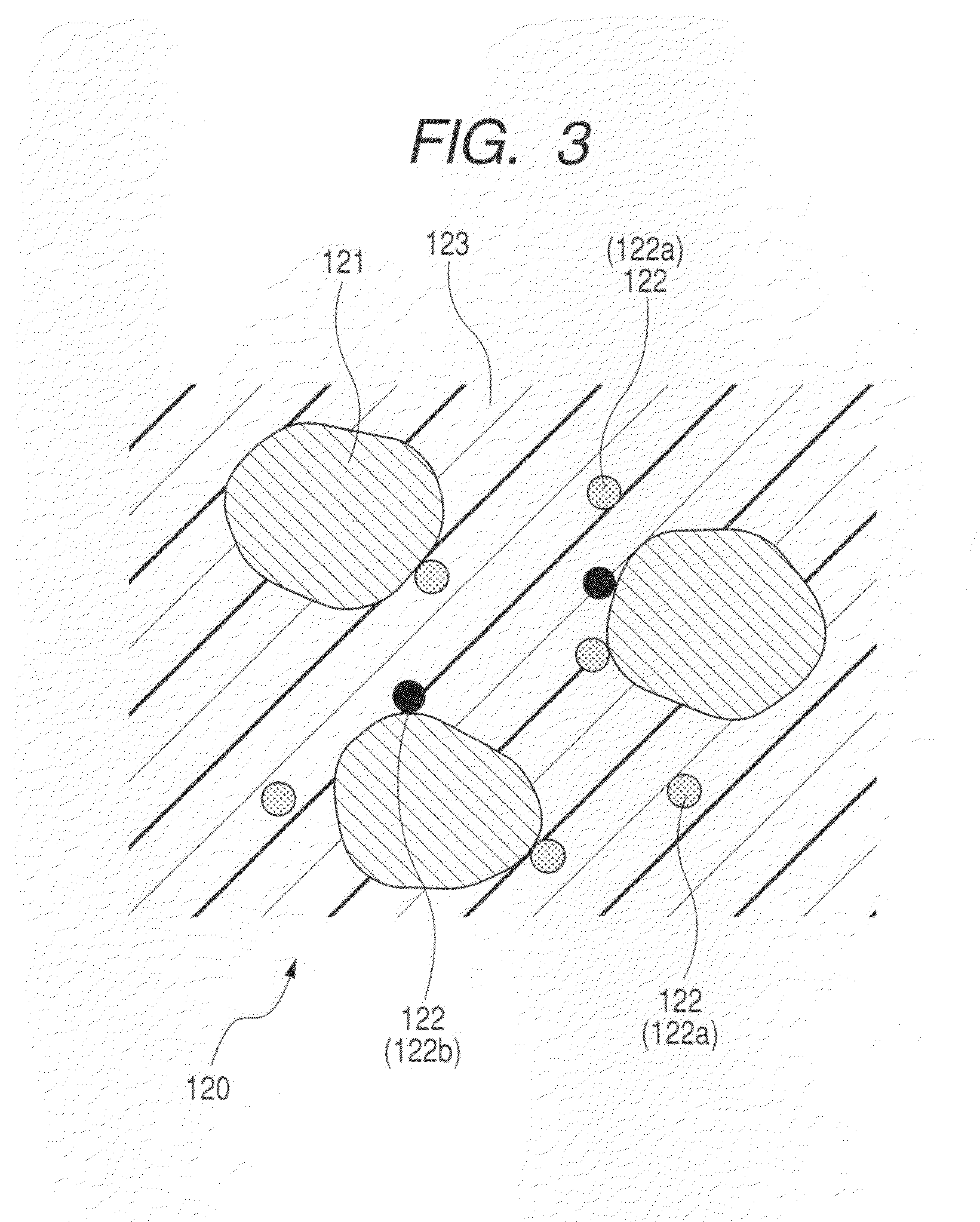
[0033]FIG. 3 is a view showing a detailed structure of the core 12 in the reactor 1 according to the first embodiment shown in FIG. 1. As shown in FIG. 3, the core 12 is made by solidifying a magnetic-powder resin mixture 120. This magnetic-powder resin mixture 120 is composed ...

second embodiment

[0087]A description will be given of the second embodiment of the present invention with reference to FIG. 5 and FIG. 6.

[0088]FIG. 5 is a graph showing a relationship between a breaking stress to be applied to the core 12 and the number of thermal cycle tests of the reactor 1 according to the second embodiment of the present invention. FIG. 6 is a graph showing a relationship between a generated stress in the core 12 and the elastic modulus of the core 12 in the reactor 1 according to the second embodiment of the present invention.

[0089]The second embodiment shows the relationship between a stress and an elastic modulus of the core in test samples (various types of reactors) as the results of thermal cycle tests.

[0090]In the second embodiment, various types of reactors as test samples having a different elastic modulus were prepared. Those test samples were cooled to minus 40 degrees (−40° C.), and heated to 150 degrees (150° C.). The above cycle (as thermal cycle test) of cooling a...


PUM

PropertyMeasurementUnit
elastic modulusaaaaaaaaaa
particle sizeaaaaaaaaaa

Abstract

A reactor is composed of a coil and a core placed in the inside area and outer peripheral area of the coil in a container. The core is composed of magnetic powder, non-magnetic powder, and resin. The nom-magnetic powder is composed of main component powder and low elastic modulus powder. The main component powder as a main component of the non-magnetic powder is made of one or more kinds of powder of a heat conductivity which is larger than that of the resin. The low elastic modulus powder is made of one or more kinds of powder of an elastic modulus which is smaller than that of the powder forming the main component powder.

Description

CROSS-REFERENCE TO RELATED APPLICATION[0001]This application is related to and claims priority from Japanese Patent Application No. 2008-291746 filed on Nov. 14, 2008, the contents of which are hereby incorporated by reference.BACKGROUND OF THE INVENTION[0002]1. Field of the Invention[0003]The present invention relates to a reactor comprised of a coil and a core placed in a container, and a method of producing the reactor for use in an electric power conversion device and the like.[0004]2. Description of the Related Art[0005]There is a known conventional reactor comprised of a coil and a core placed in a container. Japanese patent laid open publication No. JP 2006-004957 has disclosed such a conventional reactor comprised of a coil, a core placed in a container. The coil is spirally wound, and generates a magnetic flux when a current flows therein. The core is made of a resin mixture of magnetic powder and resin. The outer periphery side and the inner side of the coil in the contain...

Claims


Application Information

Patent Timeline
Patent Type & Authority Applications(United States)
IPC IPC(8): H01F27/255H01F41/06
CPCH01F17/04H01F27/22Y10T29/49071H01F2017/048H01F41/0246
Inventor SAKA, KENJIYANBE, TAKASHI
Owner DENSO CORP
Why Eureka
Try Eureka