Solid State Gyrolaser with Controlled Optical Pumping

a gyrolaser and optical pumping technology, applied in the direction of speed measurement using gyroscopic effects, instruments, surveying and navigation, etc., can solve the problems of difficult implementation of technology, high intensity of laser mode emission, and strong reduction of overall inertial performan

Inactive Publication Date: 2010-05-20
THALES SA
View PDF14 Cites 10 Cited by
  • Summary
  • Abstract
  • Description
  • Claims
  • Application Information

AI Technical Summary

Benefits of technology

[0016]The gyrolaser according to the invention has at least one feedback loop which limits or eliminates a large proportion of these problems.
[0017]More precisely, the subject of the invention is a gyrolaser comprising at least one ring-shaped optical cavity comprising at least three mirrors, a solid state amplifying medium pumped by a laser diode whose optical emission power is determined by a current supply source, the cavity and the amplifying medium being such that two so-called contra-rotating optical modes propagate in opposite directions to each other within the said optical cavity, the gyrolaser being a class B gyrolaser, the gyrolaser also comprising means of measuring the difference in optical frequency existing between the two optical modes, characterized in that the gyrolaser comprises means of measuring the total optical power circulating in the optical cavity and first means of control of the current delivered by the supply source in such a way as to maintain the total optical power subst...

Problems solved by technology

This technology, which is difficult to implement, has a certain number of disadvantages.
When the speed of rotation of the solid state gyrolaser is such that the beat frequency is equal to or very close to th...

Method used


Image

  • Solid State Gyrolaser with Controlled Optical Pumping
  • Solid State Gyrolaser with Controlled Optical Pumping
  • Solid State Gyrolaser with Controlled Optical Pumping

Examples


Embodiment Construction

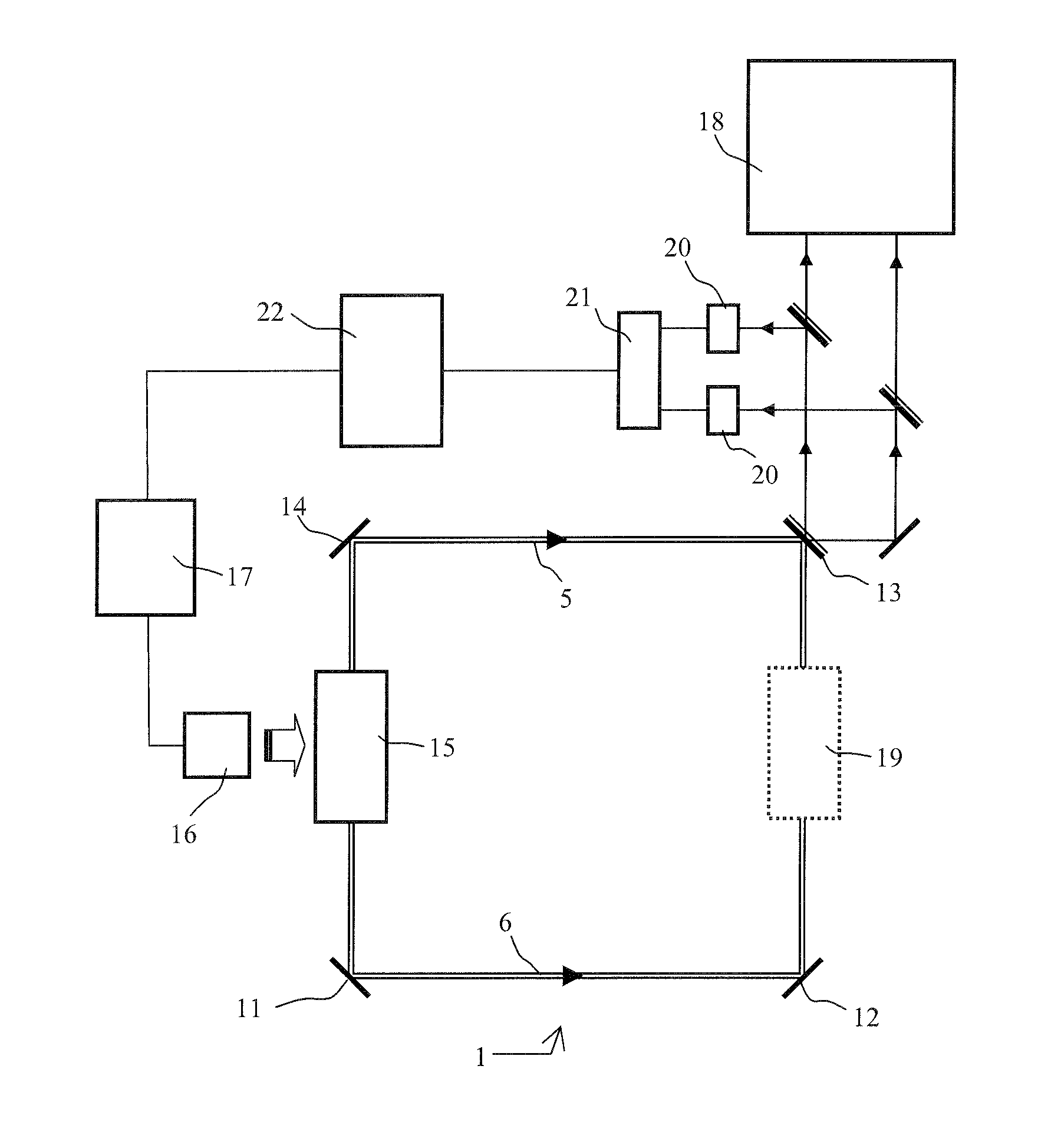
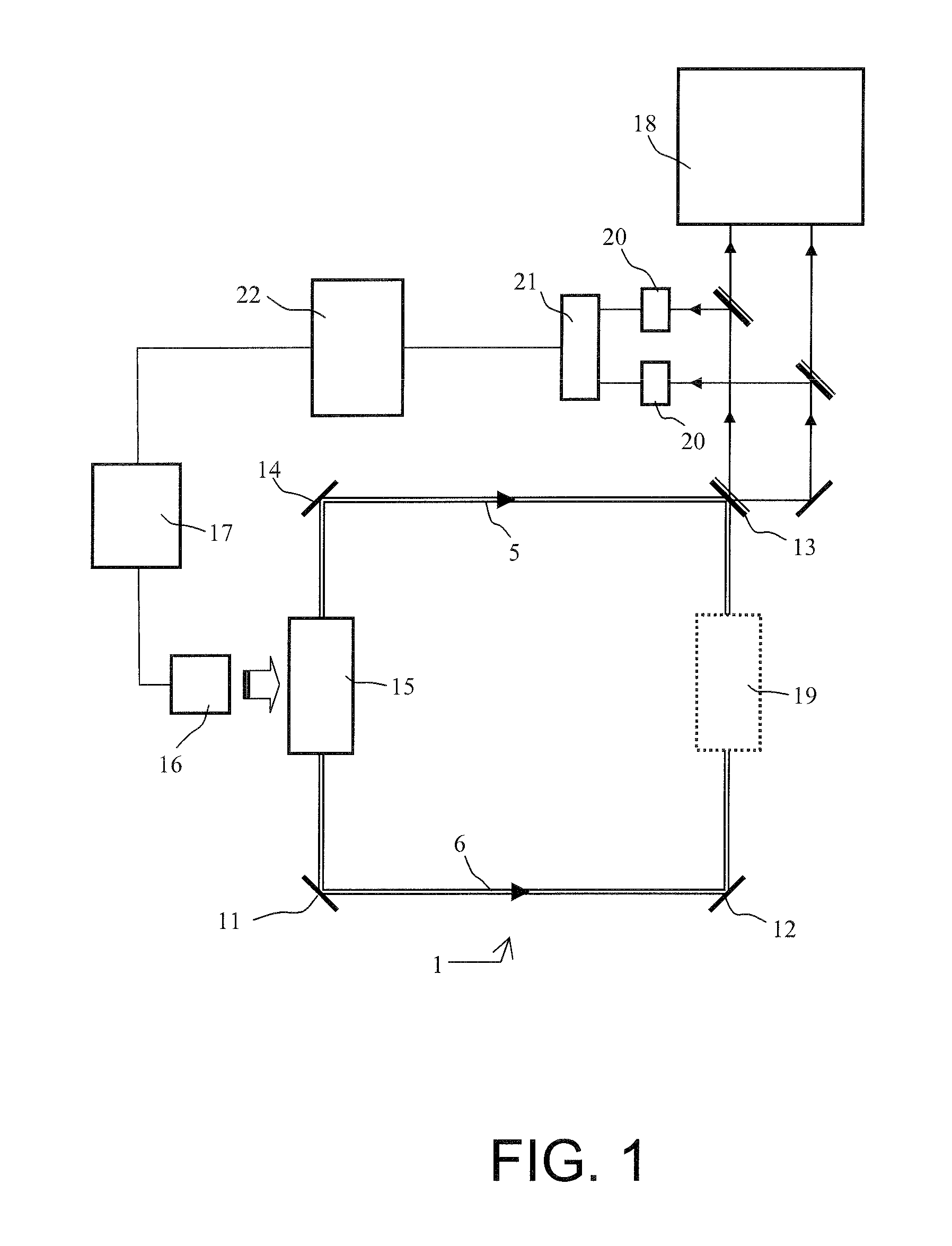
[0022]It is advantageous, before describing an embodiment of a gyrolaser, to recall the functioning of a class B laser. In the context of a simplified model, a class B laser can be described by the two real parameters E and N respectively representing the electrical field inside the cavity and the population inversion or gain of the laser. These two parameters obey the following semi-conventional differential equations (B):

Et=-γ2·E+σl2T·NEandNt=W-NT1-aE2N2T1where

[0023]σ represents the effective laser emission cross-section;

[0024]l is the effective length of the gain medium;

[0025]T is the time taken by a photon to pass through the cavity;

[0026]W is the optical pumping rate;

[0027]with

η=WσlT1γT-1

and α being the saturation parameter.

[0028]With these notations, and furthermore introducing the lifetime of the coherences T2, the conditions (C) for having a class B laser are written:

T1>>T2 and T1>>γ−1

[0029]As a non-limiting example, for a solid state ring laser whose cavity has a perimeter...


PUM


Abstract

The general field of the invention is that of gyrolasers comprising at least one ring-shaped optical cavity comprising at least three mirrors, a solid state amplifying medium pumped by a laser diode whose optical emission power is determined by a current supply source, the cavity and the amplifying medium being such that two so-called contra-rotating optical modes propagate in opposite directions to each other within the said optical cavity, the gyrolaser being a class B gyrolaser, the gyrolaser also comprising means of measuring the difference in optical frequency existing between the two optical modes. The gyrolaser comprises means of measuring the total optical power circulating in the optical cavity and first means of control of the current delivered by the supply source in such a way as to maintain the total optical power substantially constant in a narrow spectral band centred on the relaxation frequency of the laser.

Description

PRIORITY CLAIM[0001]This application claims priority to French Patent Application Number 08 06445, Solid State Gyrolaser with Controlled Optical Pumping, filed on Nov. 18, 2008.BACKGROUND OF THE INVENTION[0002]1. Field of the Invention[0003]The field of the invention is that of solid state gyrolasers used for the production of inertial systems necessary for the navigation of certain types of vehicles, such as aircraft. Gyrolasers are optical rotation sensors based on the Sagnac effect. The Sagnac effect, which is well known to specialists in this technical field, is not described in detail here. It is simply recalled that, when two contra-rotating optical modes circulate in a ring laser having a rotational movement, their optical frequencies undergo a shift representative of the speed of rotation.[0004]2. Description of the Prior Art[0005]At present, commercially available gyrolasers use a gaseous mixture of helium and neon as an amplifying medium. This technology, which is difficul...

Claims


Application Information

Patent Timeline
IPC IPC(8): G01C19/64G01P3/36
CPCG01C19/665G01C19/66
Inventor SCHWARTZ, SYLVAINFEUGNET, GILLESGUTTY, FRANCOISBONNAUDET, ETIENNEALOUINI, MEHDIPOCHOLLE, JEAN-PAUL
Owner THALES SA
Why Eureka
Try Eureka