Recording element substrate and recording head including recording element substrate

a technology of recording element substrate and recording element substrate, which is applied in the direction of data recording, instruments, printing, etc., can solve the problem of likely error in the operation of logic circuit, and achieve the effect of preventing the influence of hea

Active Publication Date: 2010-05-20
CANON KK
View PDF13 Cites 10 Cited by
  • Summary
  • Abstract
  • Description
  • Claims
  • Application Information

AI Technical Summary

Benefits of technology

[0007]The present invention is directed to a recording element substrate including a heater capable of preventing the influence of heat generated from a sub-heater on a circuit of the recording element substrate and controlling the temperature of the recording element substrate.

Problems solved by technology

As a result of the simulation, one period was about 65 ns (nanosecond) at a temperature of 25° C. and one period was about 90 ns at a temperature of 100° C. The period at a temperature of 100° C. was 1.5 times longer than that at a temperature of 25° C. Thus, when the response speed of a logic circuit is decreased by heat, an error is likely to occur in the operation of the logic circuit.

Method used


Image

  • Recording element substrate and recording head including recording element substrate
  • Recording element substrate and recording head including recording element substrate
  • Recording element substrate and recording head including recording element substrate

Examples


Embodiment Construction

[0024]Various exemplary embodiments, features, and aspects of the invention will be described in detail below with reference to the drawings.

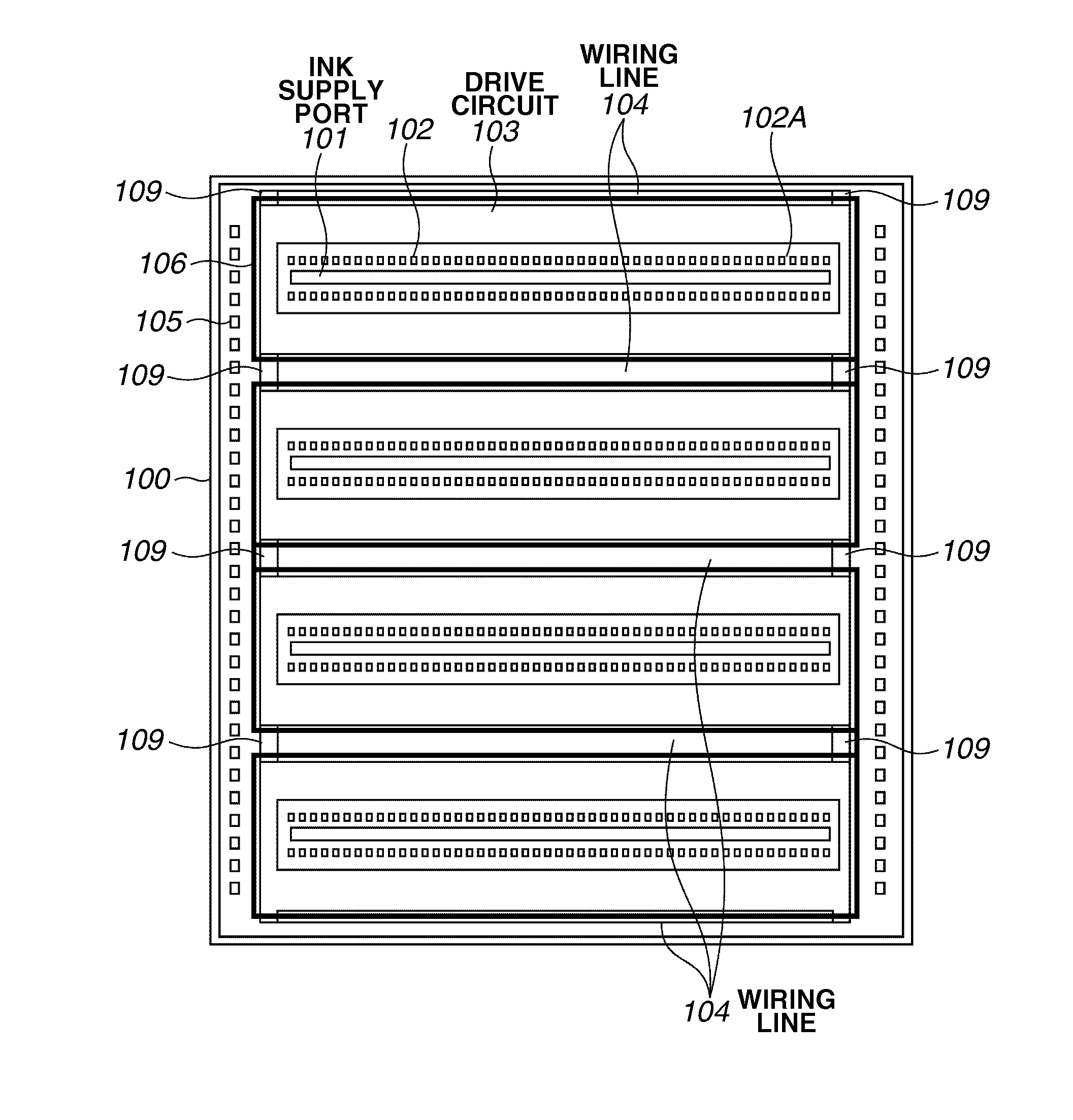
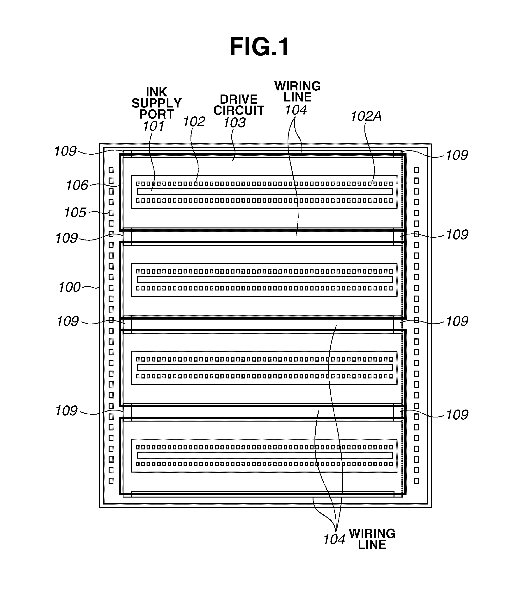
[0025]FIG. 1 is a layout diagram illustrating the surface of a recording element substrate 100 according to a first exemplary embodiment of the invention as viewed from the vertical direction (upper or lower side). Heaters 102 constitute a heater array 102A arranged as illustrated in FIG. 1. A drive circuit 103 includes a transistor or a logic circuit that drives the heaters 102. The logic circuit includes, for example, a shift register and a decoder. A wiring area 104 includes a power line for supplying power and a signal line for supplying a control signal. An external signal or power is input through terminals 105. The wiring area 104 includes a signal line for supplying the signal from the terminal 105 to the drive circuit 103. A capacitive element 109 is connected to, for example, the signal line or the power line that connects the termina...


PUM

PropertyMeasurementUnit
temperatureaaaaaaaaaa
poweraaaaaaaaaa

Abstract

A recording element substrate includes a recording element array including a plurality of recording elements, a drive circuit configured to drive the recording elements, and a heater located to surround the recording element array as viewed in a direction perpendicular to a surface of the recording element substrate and located above or below a capacitive element or a resistive element included in the drive circuit as viewed on a cross section of the recording element substrate.

Description

BACKGROUND OF THE INVENTION[0001]1. Field of the Invention[0002]The present invention relates to a recording element substrate and a recording head including the recording element substrate.[0003]2. Description of the Related Art[0004]FIG. 8 is a diagram illustrating the structure of a recording element substrate discussed in Japanese Patent Application Laid-Open No. 2002-79671. A substrate 300 includes a heater and a drive circuit that are integrally formed by a semiconductor process. A heater array 302A including a plurality of heaters is arranged along an ink supply port 301. A sub-heater 301 heats the substrate 300 and a temperature detection unit 304 detects the temperature of the substrate 300. Power or signals are input from the outside of the substrate 300 to terminals 305. A drive circuit 303 drives the heaters.[0005]As described above, the drive circuit 303 includes a metal-oxide semiconductor (MOS) transistor whose operation characteristics are changed by heat. Therefore,...

Claims


Application Information

Patent Timeline
Patent Type & Authority Applications(United States)
IPC IPC(8): G11B21/02
CPCB41J2/04528B41J2/04543B41J2/04563B41J2002/14403B41J2/14072B41J2/14129B41J2/0458
Inventor KUDO, TOMOKOFURUKAWA, TATSUOHIRAYAMA, NOBUYUKIKASAI, RYO
Owner CANON KK
Why Eureka
Try Eureka