Cooling device for light emitting device package of vibration generating machine and head lamp for vibration generating machine

Active Publication Date: 2010-05-20
SAMSUNG ELECTRONICS CO LTD
View PDF2 Cites 6 Cited by
  • Summary
  • Abstract
  • Description
  • Claims
  • Application Information

AI Technical Summary

Benefits of technology

[0034]The cooling device for a light emitting device package used for the vibration generating machine and the head lamp of the vibration generating machine according to the present invention exhibit a better cooling efficiency than the passive cooling method using only a heat sink and have a simpler structure than that of forcible cooling method using a cooling fan or a pump.
[0035]In addition, with the cooling device for a light emi

Problems solved by technology

However, the passive cooling method using the heat sink has a low cooling efficiency, and the

Method used


Image

  • Cooling device for light emitting device package of vibration generating machine and head lamp for vibration generating machine
  • Cooling device for light emitting device package of vibration generating machine and head lamp for vibration generating machine
  • Cooling device for light emitting device package of vibration generating machine and head lamp for vibration generating machine

Examples


Embodiment Construction

[0044]Exemplary embodiments of the present invention will now be described in detail with reference to the accompanying drawings. The invention may however be embodied in many different forms and should not be construed as limited to the embodiments set forth herein. Rather, these embodiments are provided so that this disclosure will be thorough and complete, and will fully convey the scope of the invention to those skilled in the art.

[0045]In the drawings, the shapes and dimensions may be exaggerated for clarity, and the same reference numerals will be used throughout to designate the same or like components.

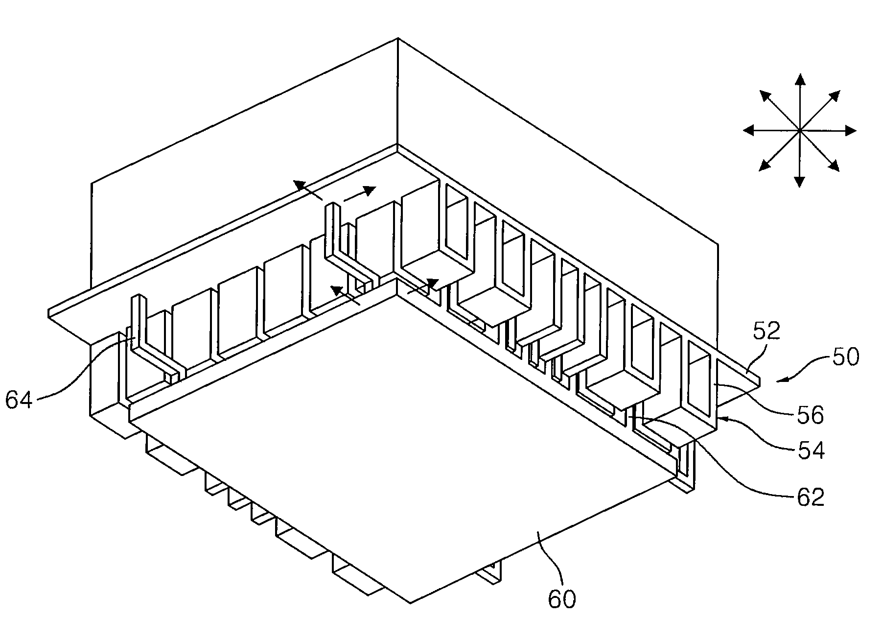
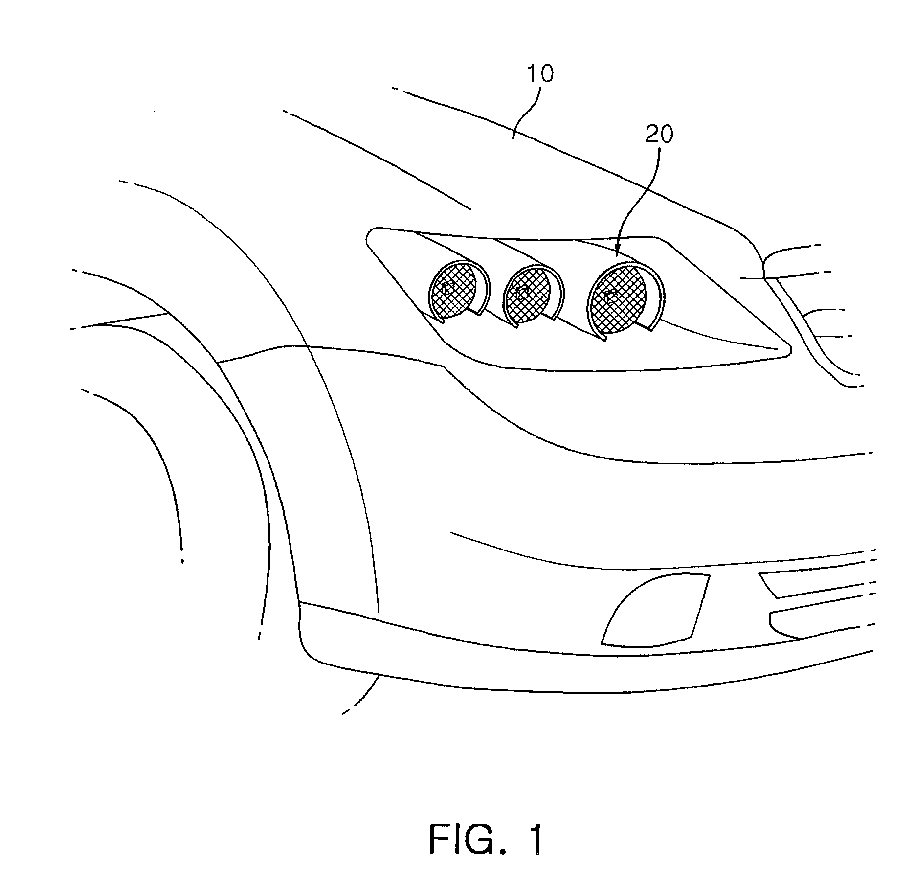
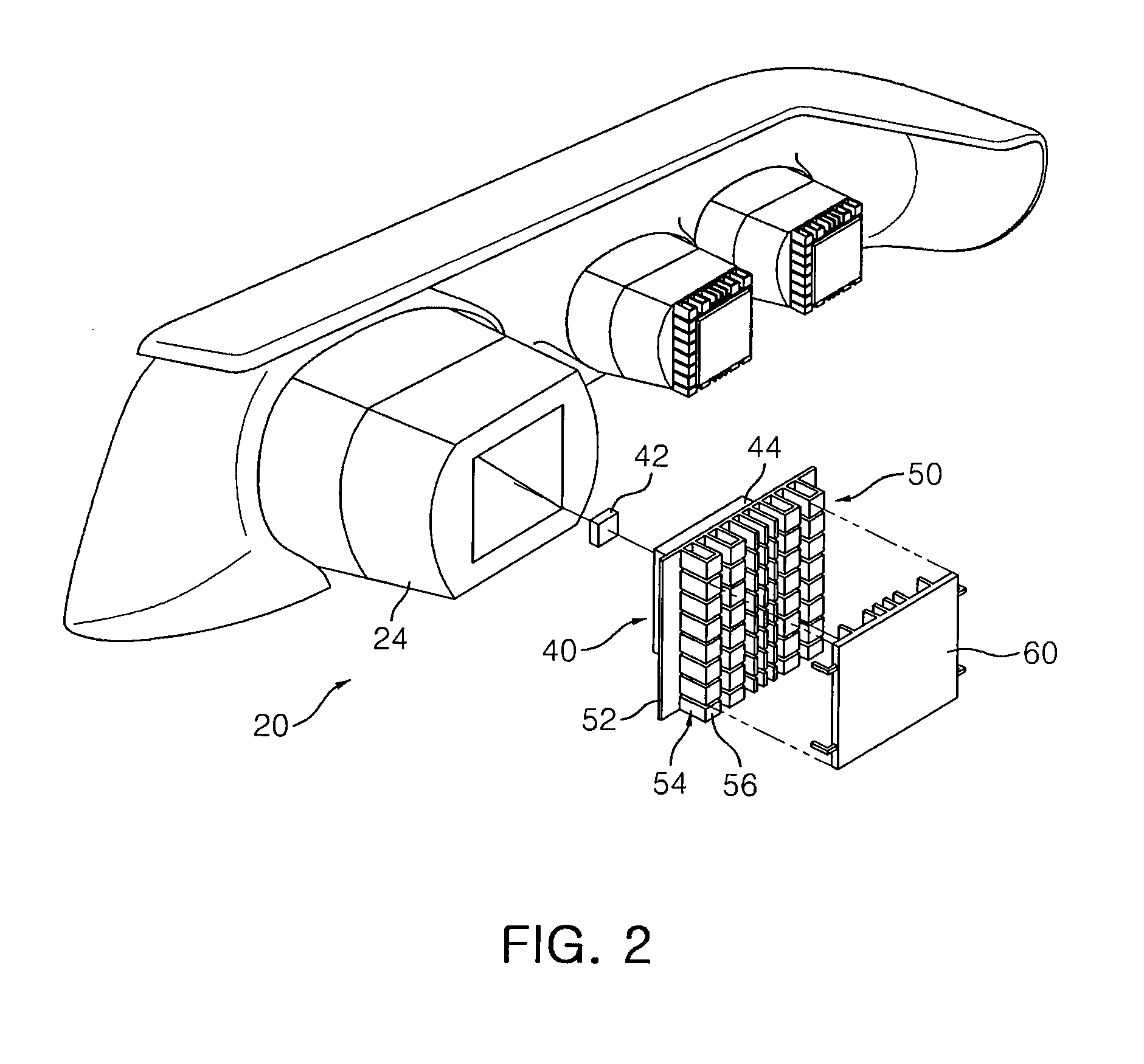
[0046]FIG. 1 is a schematic perspective view illustrating a cooling device for a light emitting device package of a vibration generating machine mounted at a head lamp of the vibration generating machine according to an embodiment of the present invention, and FIG. 2 is a rear exploded perspective view illustrating the cooling device for the light emitting device package of the...


PUM


Abstract

A cooling device for a light emitting device package of a vibration generating machine, includes: a heat releasing plate provided at one side of the light emitting device package; a vibrator disposed to face the heat releasing plate and vibrating to generate an air flow according to vibration of the vibration generating machine; and a vibration transfer unit configured to connect the vibrator and the heat releasing plate to allow the air flow generated from the vibrator to be transferred to the heat releasing plate so as to be cooled.

Description

CROSS-REFERENCE TO RELATED APPLICATIONS[0001]This application claims the priority of Korean Patent Application No. 2008-0115397 filed on Nov. 19, 2008, in the Korean Intellectual Property Office, the disclosure of which is incorporated herein by reference.BACKGROUND OF THE INVENTION[0002]1. Field of the Invention[0003]The present invention relates to a cooling device for a light emitting device package of a vibration generating machine and a head lamp for the vibration generating machine, and more particularly, to a cooling device for a light emitting device package for a vibration generating machine capable of cooling the light emitting device package used for the vibration generating machine by using vibration of the vibration generating machine itself, and a head lamp for the vibration generating machine.[0004]2. Description of the Related Art[0005]In general, a light emitting element (e.g., a light emitting diode, etc.) refers to a diode that emits excessive energy as light when...

Claims


Application Information

Patent Timeline
IPC IPC(8): F21V29/00F28F13/12
CPCB61D29/00F21S48/115F21S48/325F21V29/02F21W2101/02F21W2101/10H01L2924/0002F21Y2101/02F28F13/00H01L2924/00F21Y2115/10F21S41/143F21S41/151F21S45/43F21W2107/10B60Q1/04F21V29/63F21W2102/00
Inventor LEE, YOUNG KICHOI, SEOG MOONSHIN, SANG HYUNGAO, SHANKIM, JONG WOON
Owner SAMSUNG ELECTRONICS CO LTD
Why Eureka
Try Eureka