Eureka AIR delivers breakthrough ideas for toughest innovation challenges, trusted by R&D personnel around the world.

Method for applying and dimensioning an abradable coating

Active Publication Date: 2010-05-20
GENERAL ELECTRIC CO
View PDF6 Cites 2 Cited by
  • Summary
  • Abstract
  • Description
  • Claims
  • Application Information

AI Technical Summary

Problems solved by technology

Maintaining a minimum clearance prevents unwanted “leakage” of a hot gas over tip of the buckets, increased clearances lead to leakage problems and cause significant decreases in overall efficiency of the turbine.
However, it should be appreciated that if bucket tips rub against a particular location of the shroud such that the bucket tip is eroded, the erosion of the bucket tip increases clearances between bucket tip and shroud in other locations, again resulting in unwanted leakage.
The need to maintain adequate clearance without significant loss of efficiency is made more difficult by the fact that as the turbine rotates, centrifugal forces acting on the turbine components can cause the buckets to expand in an outward direction toward the shroud, particularly when influenced by the high operating temperatures.
Later, during normal operation the clearance decreases due to the centrifugal forces and temperature changes in rotating and stationary components inevitably resulting in at least some radial extension of the bucket tips, causing them to contact the coating on the shroud and wear away a part of the coating to establish the minimum running clearance.
However, manufacturing a shroud to include the concave profile, or any desired profile, can be difficult and expensive.

Method used


Image

  • Method for applying and dimensioning an abradable coating
  • Method for applying and dimensioning an abradable coating
  • Method for applying and dimensioning an abradable coating

Examples


Embodiment Construction

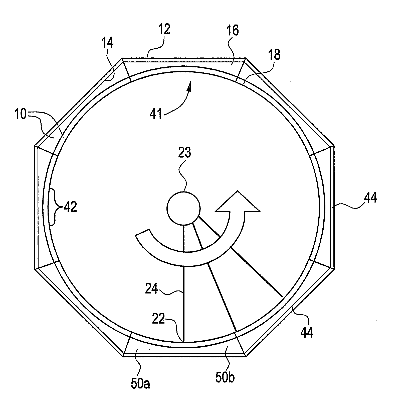
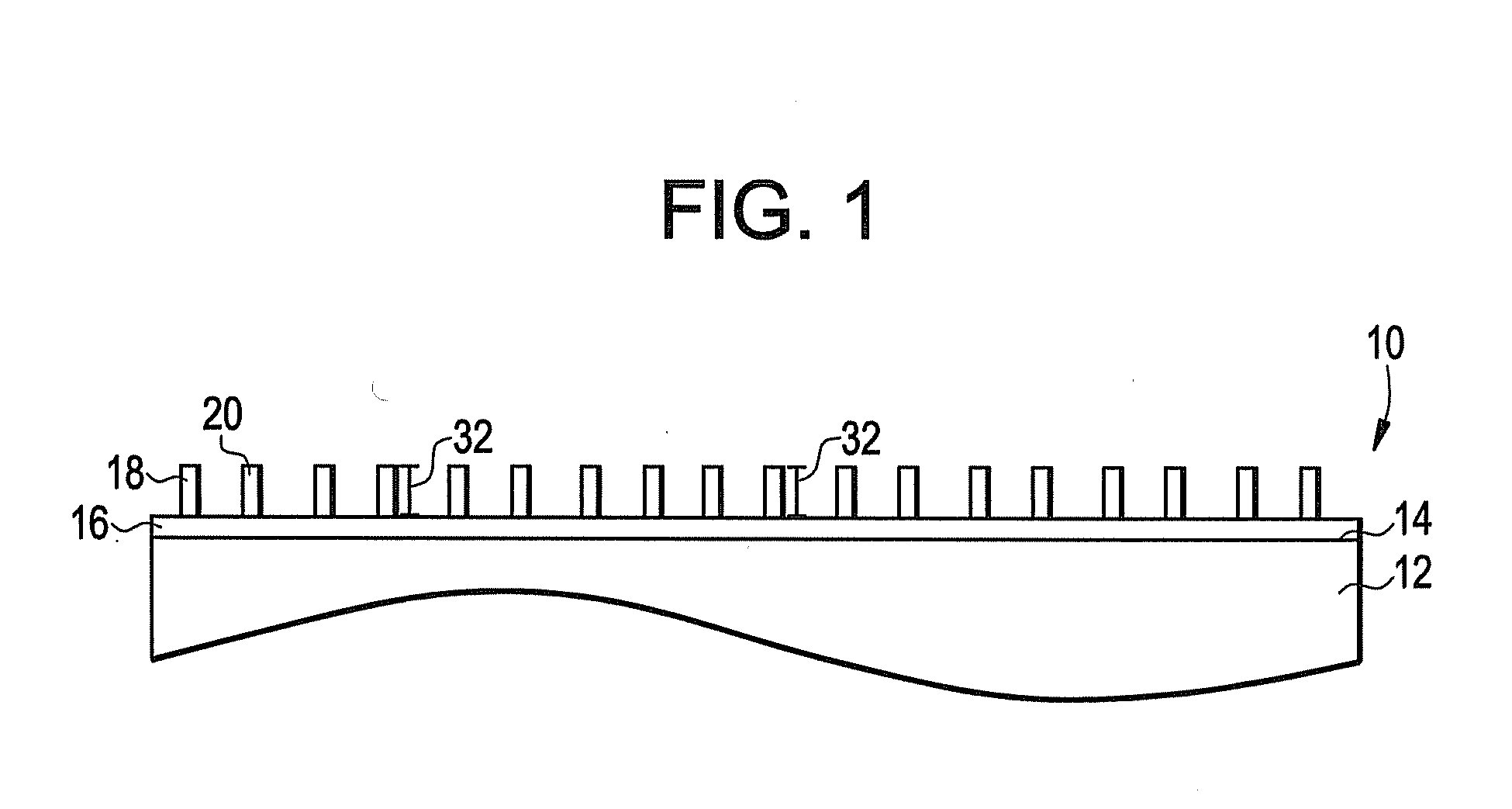
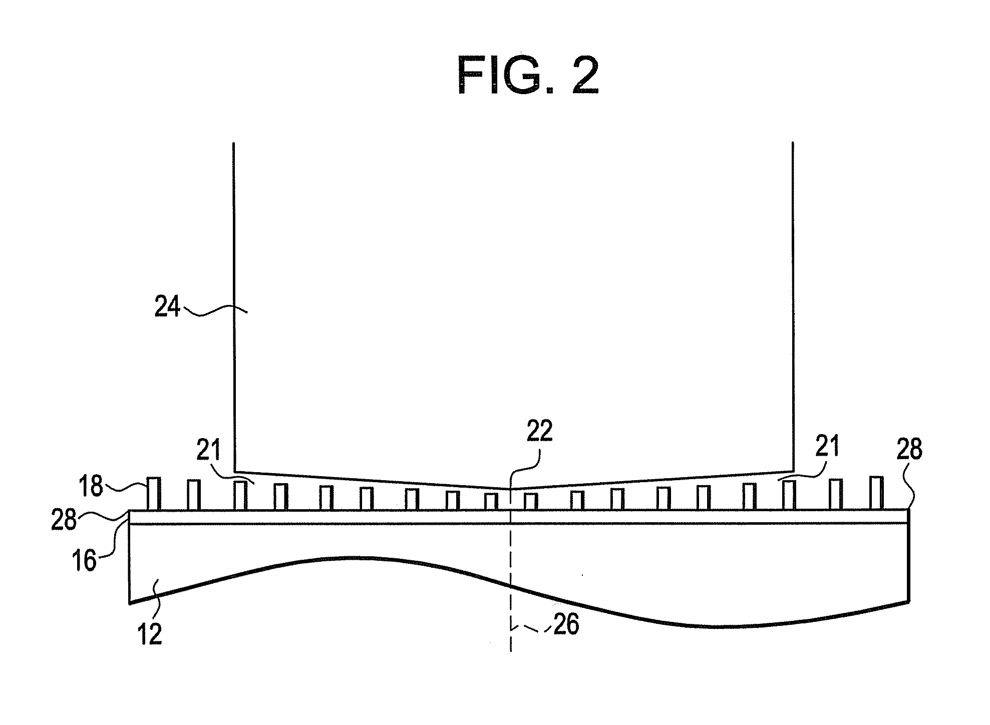
[0020]Referring to FIG. 1, a substrate coating, such as an abradable coating 10, is shown applied to a substrate 12 including a substantially flat surface 14, wherein the coating 10 is applied in at least one substrate layer, such as abradable layers 16 and 18. In an exemplary embodiment, the substrate 12 is a turbine shroud, to which the coating 10 is applied in an adhering layer and a patterned layer. Though the substrate 12 will not be limited to a turbine shroud, and the at least one layer 16 and 18 will not be limited to an adhering layer and a patterned layer, for purposes of clarity and simplicity, the substrate 12 will be referred to as the shroud 12, and the at least one layer 16 and 18 will be referred to as the adhering layer 16 and the patterned layer 18 hereinafter.

[0021]The adhering layer 16 is applied to the substantially flat surface 14 of the shroud 12, which will typically be environmental barrier coated (EBC). The adhering layer 16 may be a metallic bond coat, suc...


PUM

PropertyMeasurementUnit
Fractionaaaaaaaaaa
Heightaaaaaaaaaa

Abstract

Disclosed is a coated substrate including a substrate coating applied to at least one substantially flat surface of the substrate, the coating including at least one of an axial concavity and a circumferential curvature, the substrate being configured for disposal parametrically about a moving component.

Description

FIELD OF THE INVENTION[0001]The disclosure relates generally to a method for applying an abradable coating to a substrate, and more specifically to a method for applying and dimensioning the abradable coating.BACKGROUND OF THE INVENTION[0002]In a gas turbine engine, in order to achieve maximum engine efficiency (and corresponding maximum electrical power generation), it is important that the buckets rotate within the turbine casing or “shroud” with minimal interference and with the highest possible efficiency relative to the amount of energy available from the expanding working fluid. Typically, highest operation efficiencies can be achieved by maintaining a minimum threshold clearance between the shroud and tips of the bucket. Maintaining a minimum clearance prevents unwanted “leakage” of a hot gas over tip of the buckets, increased clearances lead to leakage problems and cause significant decreases in overall efficiency of the turbine. However, it should be appreciated that if buc...

Claims


Application Information

Patent Timeline
IPC IPC(8): F01D11/12F01D11/08
CPCF01D11/122F05D2230/31F05D2230/90
Inventor JOHNSON, CURTIS ALANLAU, YUK-CHIUMARGOLIES, JOSHUA LEEROBERTS, III, HERBERT CHIDSEY
Owner GENERAL ELECTRIC CO
Why Eureka
Eureka Blog
Learn More