
Cutting device and cutting method for printed products

a cutting device and printing technology, applied in the field of cutting devices and cutting methods, can solve the problems of increasing the risk of damage to the cutting device, failure of the cutting device, and inability to cut, so as to achieve the effect of improving the cutting quality and the service life of the kni

Inactive Publication Date: 2010-05-27
FERAG AG
View PDF0 Cites 7 Cited by
  • Summary
  • Abstract
  • Description
  • Claims
  • Application Information

AI Technical Summary

Benefits of technology

The present invention aims to improve the cutting quality and service life of knives in high-performance systems using the shear-cutting method. The problem is that the cutting clearance between the knives is very small and dependent on the type of material being cut, and the current method of grinding the knives only addresses the issue of downtime and not the actual problem of wear and tear on the blades. Additionally, the current methods of grinding and replacing the knives are not optimal for cutting printed products. The invention provides a cutting apparatus and method with a knife arrangement that is designed for high-performance shear cutting, improving cutting quality and service life.

Problems solved by technology

The above document explains that it is a particular problem of shear cutting that the cutting principle requires a very small and highly precise so-called cutting clearance.
A further disadvantage is the fact that the abrasive regrinding of the knives takes place in the cutting station itself and therefore abrasive residues, grinding material and very small hard-metal filings remain in the cutting subassembly and thus increase the risk of damage to, and failure of, the cutting device.
Overall, the method described in EP 1 510 288, and the rotary cutting machine claimed therein is not able to overcome the actual problem; rather, in the manner of controlling symptoms, only a single aspect of the maintenance problem is tackled.

Method used


Image

  • Cutting device and cutting method for printed products
  • Cutting device and cutting method for printed products
  • Cutting device and cutting method for printed products

Examples


Embodiment Construction

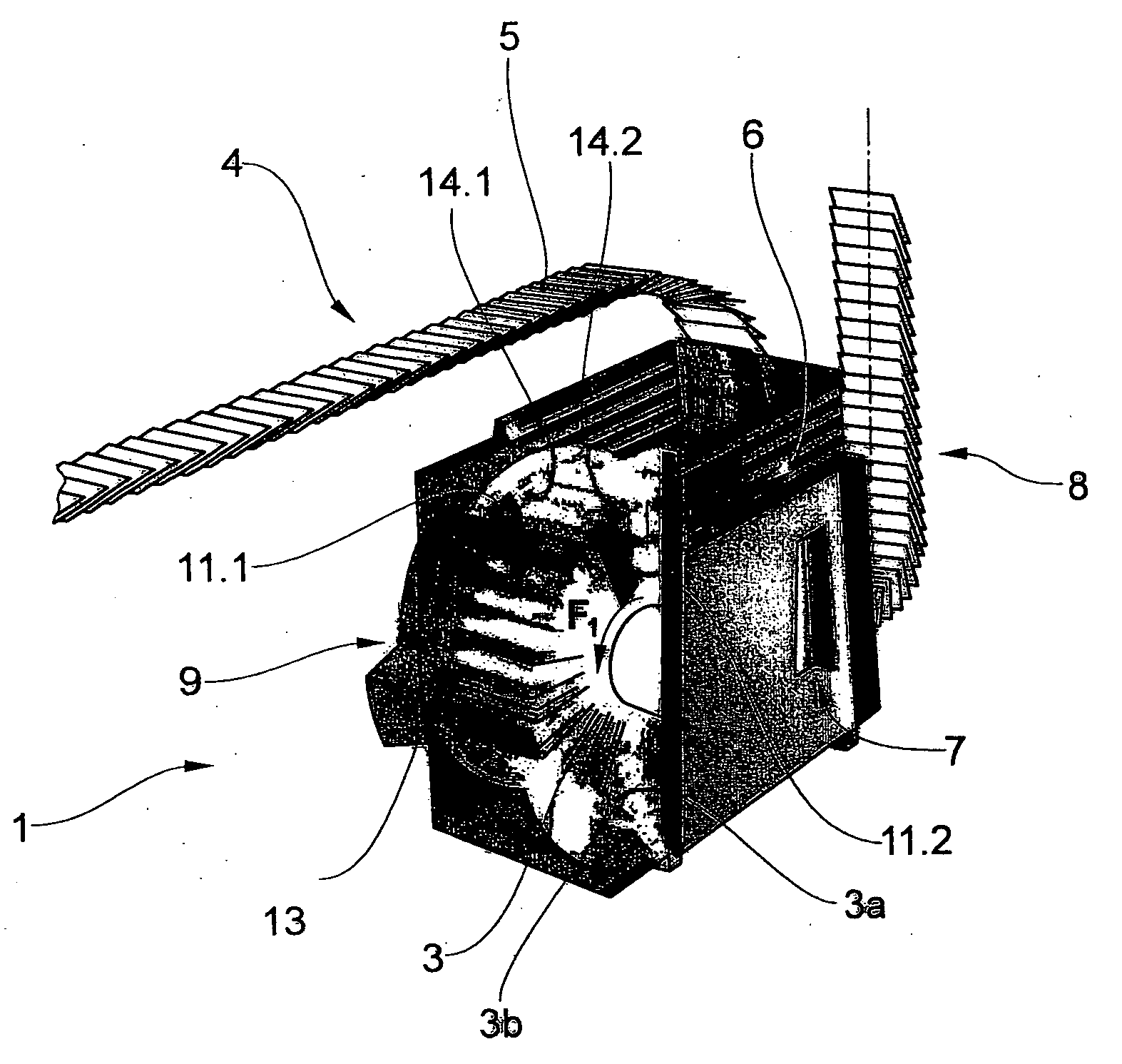
[0035]FIG. 1 shows a conventional cutting-drum machine 1 with a drum rotor 2 which has a plurality of cells 3 revolving around its periphery. Each cell has a leading and trailing cell wall 3a, 3b. A feed conveyor 4 transports printed products 5, in this case in the form of an imbricated stream (scaled stream), to the cutting-drum machine 1. The printed products 5 are separated and fed, in a transfer region 6, to the drum rotor 2, and therefore in each case one printed product 5 is introduced into each of the cells 3, which revolve in the direction of the arrow F1. The drum rotor is driven by a drive 9 (not illustrated in any more detail here). Once the drum has revolved through approximately 300°, the printed products 5 are removed again from the drum rotor 2 at a removal location 7 and are fed here, once again in an imbricated formation, by a removal conveyor 8 to any other processing steps, such as insertion, stacking or bundling.

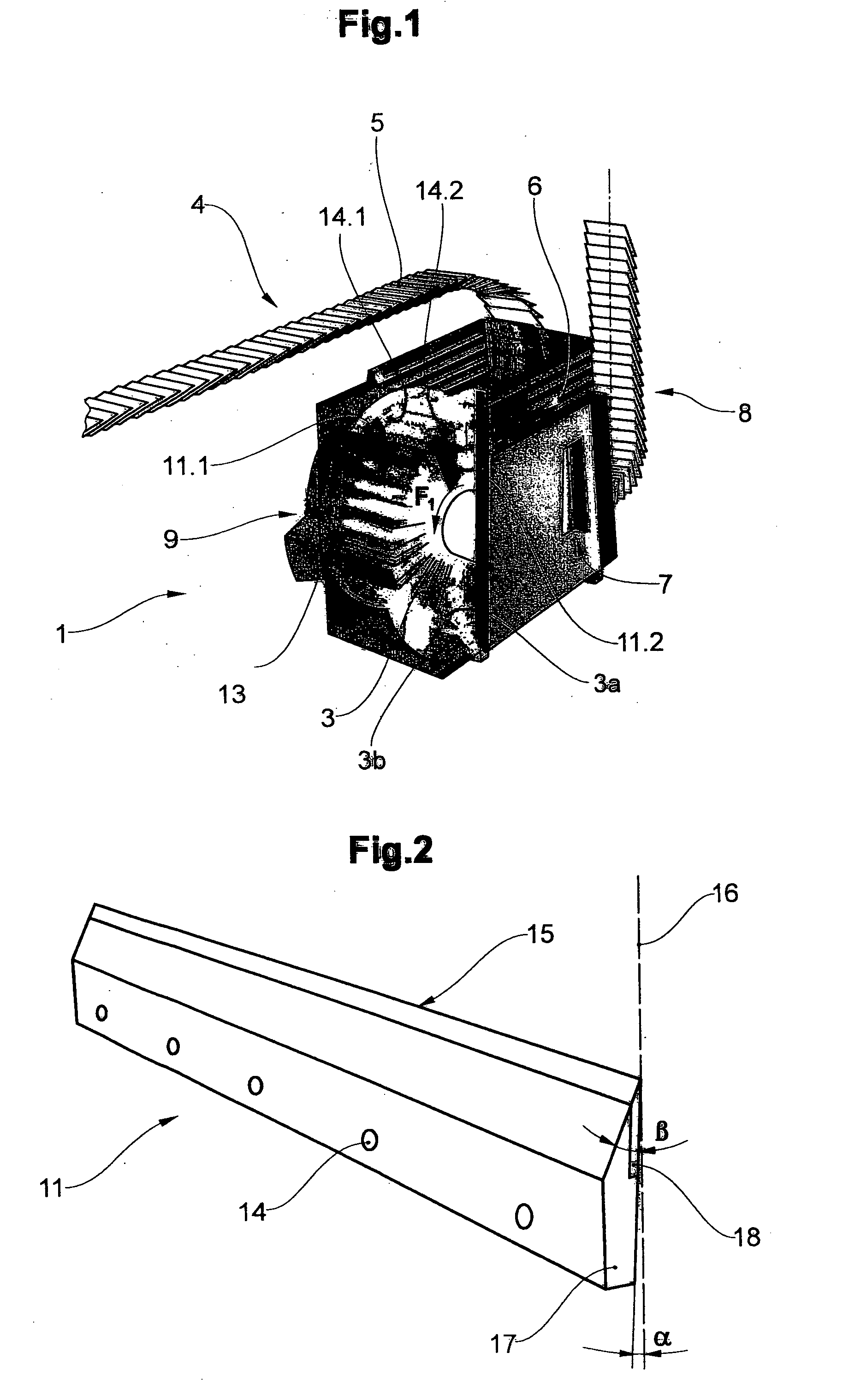
[0036]Two knives 11.1 and 11.2 are arranged, for th...


PUM

PropertyMeasurementUnit
bevel angleaaaaaaaaaa
thicknessesaaaaaaaaaa

Abstract

The invention relates to a cutting device for cutting continuously conveyed printed products (5). The cutting device has multiple conveying elements (3) which run around a closed path for conveying at least one single printed product (5) or printed product groups (5′). The printed products (5, 5′) are moved along their conveyance path past at least one cutting station (10). In each cutting station, at least one edge of the printed product (5) is cut by knife blades (11, 12) and counter blades (13, 14) in a shear cut. For this shear cut, according to the invention, multiple self-sharpening blades (11, 12) come into cutting engagement with at least one counter blade (13, 14). Alternatively, multiple counter blades (13, 14) come into cutting engagement with at least one self-sharpening blade (11, 12). A significant improvement in edge retention and cutting quality is achieved by means of targeted blade kinematics, blade arrangement, product guidance, and blade geometry.

Description

BACKGROUND OF THE INVENTION[0001]1. Field of the Invention[0002]The present invention relates to a cutting apparatus and to a cutting method.[0003]2. Discussion of Related Art[0004]Multilayered printed products, e.g. periodicals, newspapers or booklets, are usually trimmed nowadays along one or more sides. In this respect, the prior art discloses various solutions which differ by way of cutting capacity, cutting quality and various other parameters. The task of a person skilled in the art here is to determine a particular cutting method depending on requirements such as, in particular, the kind of products which are to be trimmed (type of paper, weight, thickness, page count of the product, folded or glued, printing method, etc.).[0005]Alongside so-called rotary cutting devices, as are known for example from EP 0 017 878, so-called cutting drums, which have been disclosed in the present applicant's EP 0 367 715, have proven successful in practice in recent years. In the case of rota...

Claims


Application Information

Patent Timeline
Patent Type & Authority Applications(United States)
IPC IPC(8): B26D1/20B26D7/12B26D1/22
CPCB26D1/0006B26D1/365B26D2001/006B26D2001/0053B26D2001/002Y10T83/7863Y10T83/647Y10T83/303Y10T83/04
Inventor MADER, CARL CONRAD
Owner FERAG AG
Learn More