Hull Robot

a robot and hull technology, applied in the field of hull robots, can solve the problems of increasing the cost of operating the vessel, increasing the emissions, and the vessel having to be dry docked for an extended period of time, so as to reduce the frictional resistance of the vessel, reduce the emission of carbon dioxide (co2), and reduce the cost of fuel

Active Publication Date: 2010-05-27
RAYTHEON CO
View PDF101 Cites 89 Cited by
  • Summary
  • Abstract
  • Description
  • Claims
  • Application Information

AI Technical Summary

Benefits of technology

[0009]In one aspect, a hull cleaning robot can assist in lowering the frictional resistance of the vessel. Decreased fuel costs and lower carbon dioxide (CO2) emissions are possible.
[0010]The hull cleaning robot may decrease the cost of de-fouling a vessel hull, reduce the release of antifouling paint toxins into the water during hull cleaning, and lower hull maintenance costs.
[0011]In one aspect of the subject invention, the hull cleaning robot is reliable and can be used for a variety of tasks on a variety of structures.

Problems solved by technology

The result is added cost to operate the vessel and increased emissions.
For example, hull paints and coatings are used in an effort to decrease the chance of bio-fouling, but such treatments do not always work reliably.
Also, the vessel must be dry docked for an extensive period of time while the paint and / or coating is applied.
The cost of such a cleaning procedure is high This type of cleaning effort is repeated approximately every ten to twenty months or sooner if needed.
Worse, some jurisdictions have made this practice illegal due to the toxicity of anti-fouling paint which contaminates the water.
Most prior hull cleaning robots suffer from several shortcomings.

Method used


Image

  • Hull Robot
  • Hull Robot
  • Hull Robot

Examples


Embodiment Construction

[0044]Aside from the preferred embodiment or embodiments disclosed below, this invention is capable of other embodiments and of being practiced or being carried out in various ways. Thus, it is to be understood that the invention is not limited in its application to the details of construction and the arrangements of components set forth in the following description or illustrated in the drawings. If only one embodiment is described herein, the claims hereof are not to be limited to that embodiment. Moreover, the claims hereof are not to be read restrictively unless there is clear and convincing evidence manifesting a certain exclusion, restriction, or disclaimer.

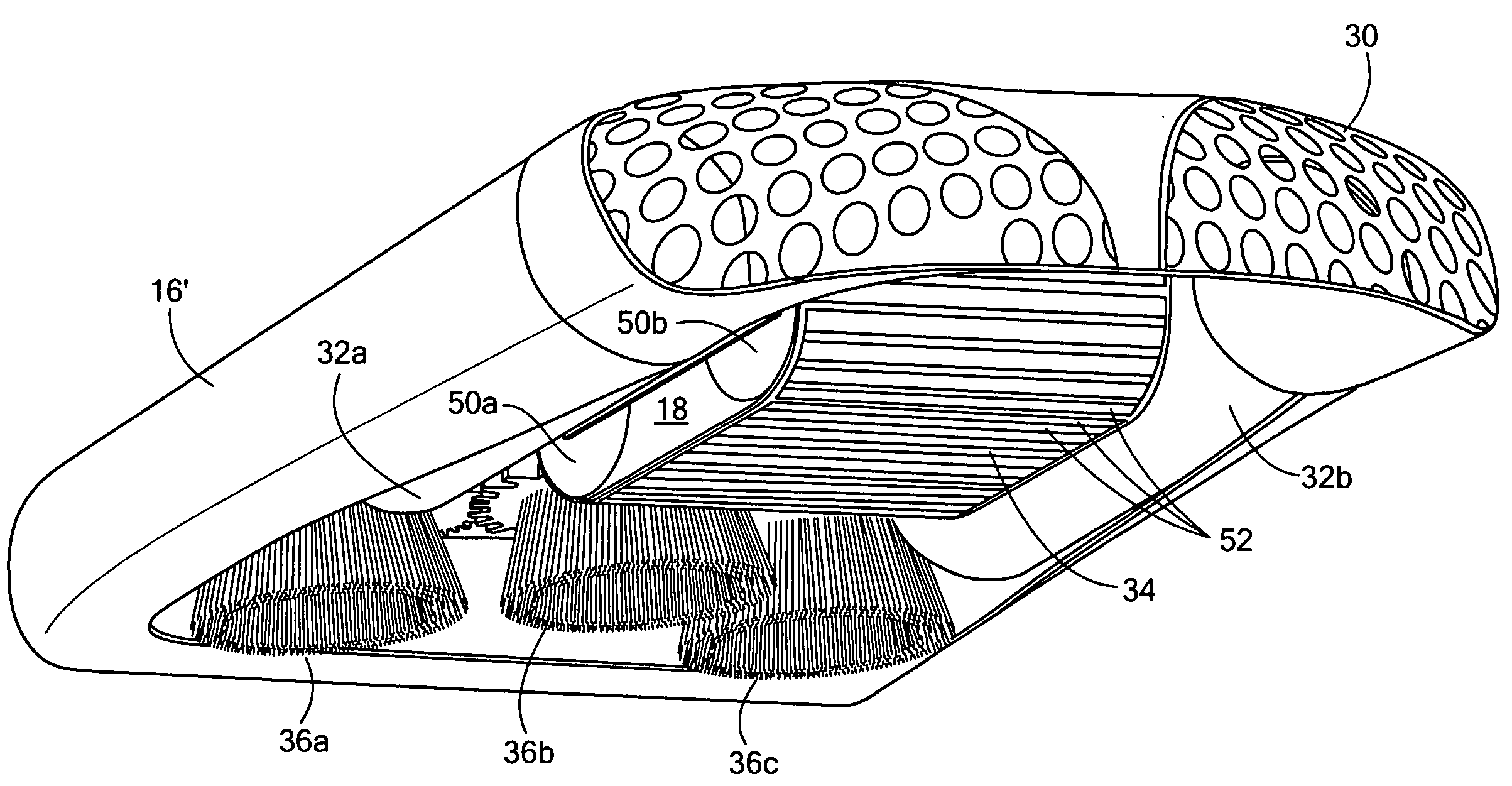
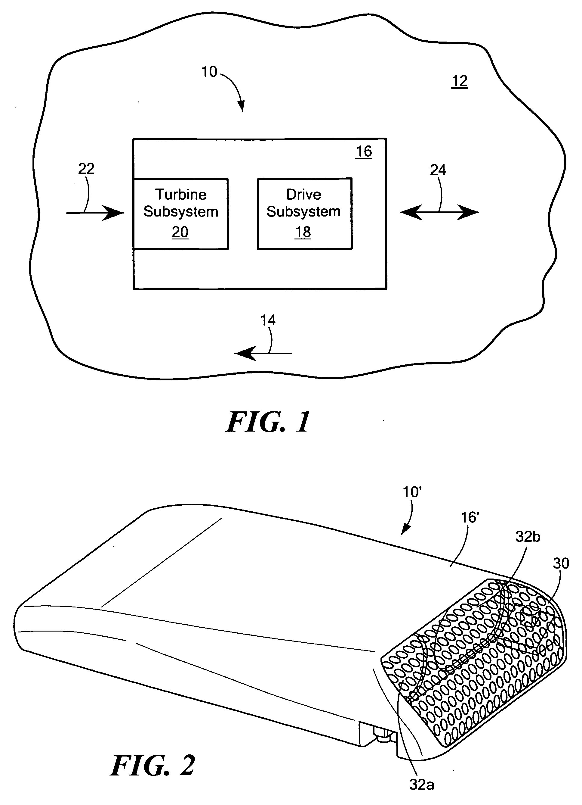
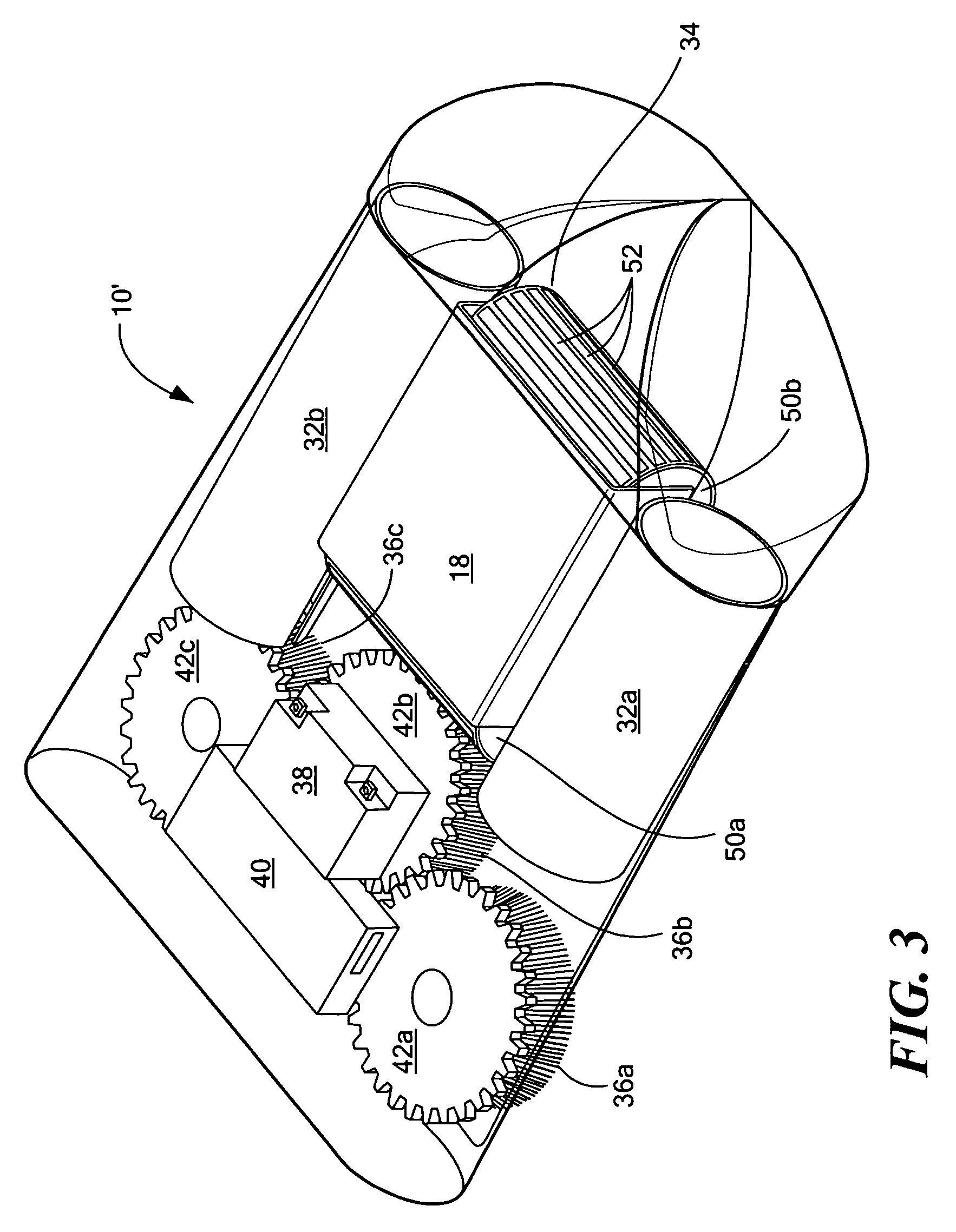
[0045]FIG. 1 shows robot 10 on vessel hull 12 (e.g., a ship) underway in the direction of vector 14. Robot body 16 houses drive subsystem 18 and turbine subsystem 20. Fluid (e.g., water) moves past hull 12 in the direction of vector 22 due to the motion of the vessel. In accordance with the subject invention, turbine subsys...


PUM


Abstract

A hull cleaning robot includes at least one cleaning apparatus for cleaning the hull of a vessel, at least one drive track holding the robot on the hull as the robot maneuvers about the hull, and at least one turbine actuatable by water flowing past the hull for operating the at least one drive track and, optionally, the cleaning apparatus.

Description

FIELD OF THE INVENTION[0001]The subject invention relates to a hull robot typically configured to clean and / or inspect the hull of a vessel.BACKGROUND OF THE INVENTION[0002]The frictional resistance of a vessel hull as it moves through the water can constitute 45% to 90% of the total resistance and may be increased by 6% up to 80% due to the fouling of the hull by algae, sea grass, barnacles, and the like. An added resistance of 30% due to moderate bio-fouling of a tanker hull can increase the fuiel consumption of the vessel by twelve tons per day. The result is added cost to operate the vessel and increased emissions.[0003]Accordingly, there are a variety of methods employed to lower the chance of bio-fouling and / or to clean the hull of vessels. For example, hull paints and coatings are used in an effort to decrease the chance of bio-fouling, but such treatments do not always work reliably. See, for example, U.S. Pat. No. 7,390,560 incorporated by reference herein. Also, the vessel...

Claims


Application Information

Patent Timeline
Patent Type & Authority Applications(United States)
IPC IPC(8): B63B59/06
CPCB63B59/10G05D1/0227Y02T70/32G05D1/0276G05D1/0274Y02T70/00
Inventor ROONEY, III, JAMES H.LONGLEY, JONATHAN T.HARRIS, JOEL N.SMITH, FRASERJACOBSEN, STEPHEN C.
Owner RAYTHEON CO
Why Eureka
Try Eureka