An engine using potential and buoyancy energy with de pressure transfer box

a technology of buoyancy energy and potential, applied in the direction of engines, hydro energy generation, motors, etc., can solve problems such as energy loss, and achieve the effect of small energy requirements

Inactive Publication Date: 2010-05-27
SABAPATHY NARAYANA THEVAR
View PDF0 Cites 17 Cited by
  • Summary
  • Abstract
  • Description
  • Claims
  • Application Information

AI Technical Summary

Benefits of technology

[0005]In this buoyancy-gravity engine (BG engine), the BG Roller travels up and down through the buoyancy column and the gravity machine. This movement is similar to a piston moving up and down in an Internal Combustion Engine. When the BG roller moves down in the gravity machine at least one wheel of the machine is rotated due to the eccentric weight of the roller in one end of the wheel. The roller then slips down automatically from the fingers of the wheel and rolls down to the mouth of the DP transfer box. The BG roller then goes into the DP Transfer box when a valve is opened. The same BG roller then goes up into the buoyancy chamber when another valve is opened. The BG roller in the buoyancy column, due to the inherent law of buoyancy, automatically reaches the top of the buoyancy column and again falls into the fingers of the gravity machine. Thus the gravity machine is continuously made to rotate due to the rollers. It should be noted that for the entire operation the energy required is very small and almost negligible.

Problems solved by technology

In conventional engines the energy required to generate power is substantially high when converted from one form to another, which also results in the loss in energy.

Method used


Image

  • An engine using potential and buoyancy energy with de pressure transfer box
  • An engine using potential and buoyancy energy with de pressure transfer box
  • An engine using potential and buoyancy energy with de pressure transfer box

Examples


Embodiment Construction

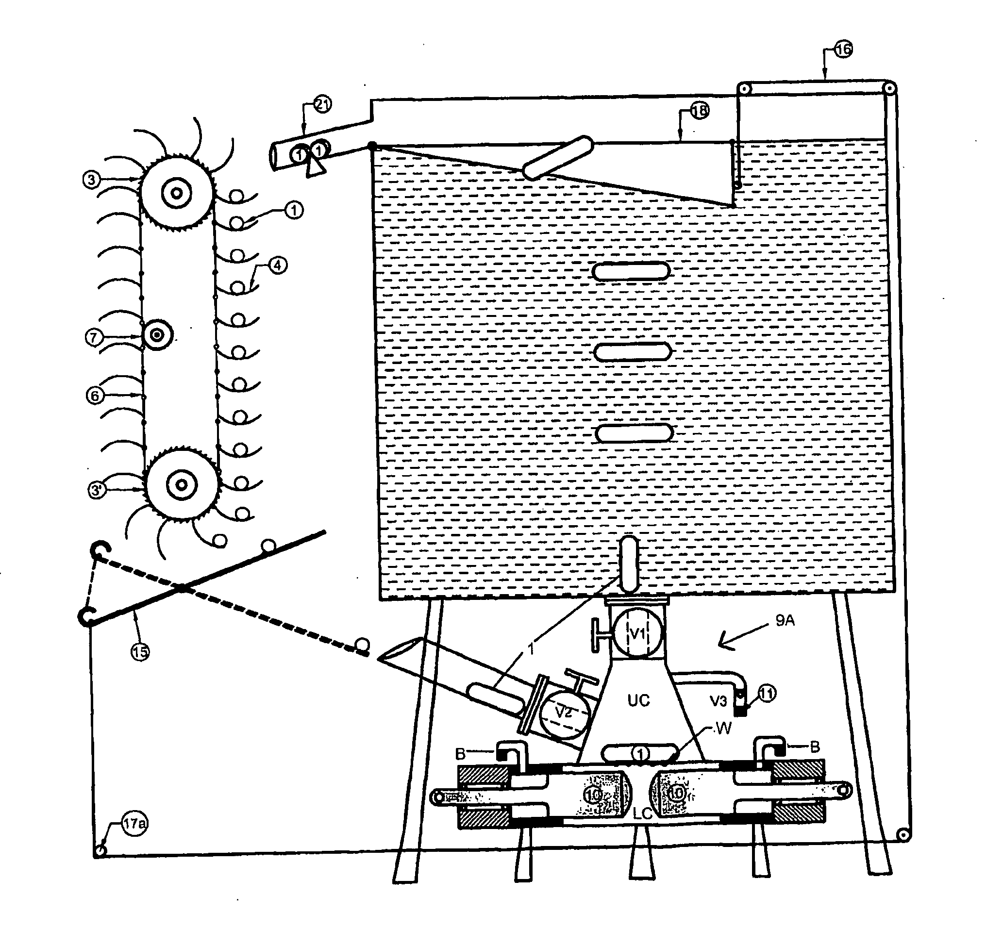
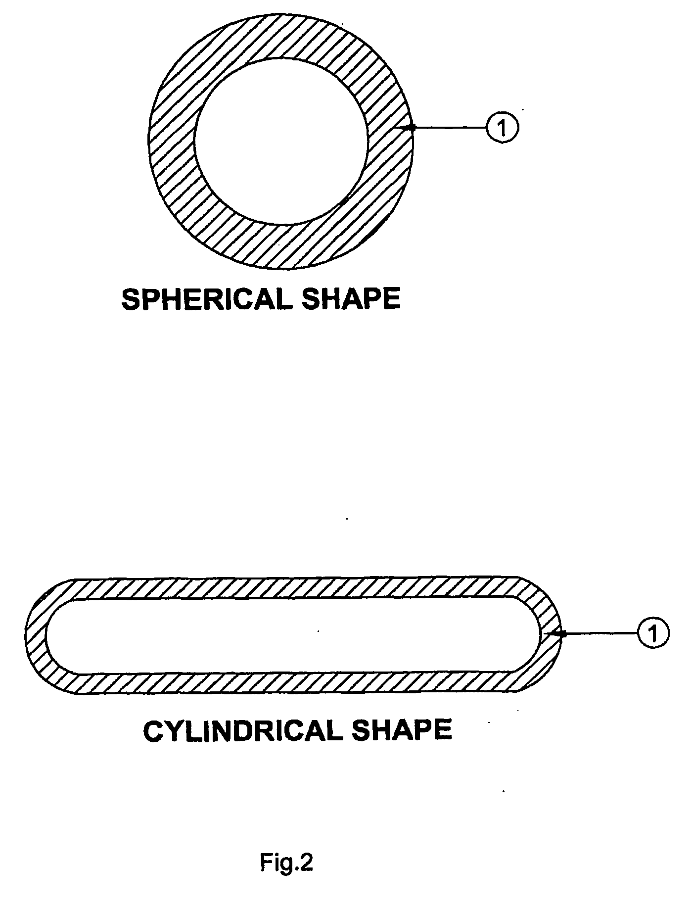
[0013]The invention can be best illustrated as seen in FIG. 1. The BG roller (1) (herein referred to as roller) are placed one by one on roller housings which are specially designed fingers (4), and are allowed to travel by its own gravitational force down the gravity machine (100). The gravity machine (100) consists of at least one wheel (3), preferably two wheels connected together by a chain. The fingers (4) are peripherally placed on the wheels (3) to hold the rollers (1). Due to the eccentric weight of the rollers (1) placed on the peripheral of the wheel (3), the wheel (3) begins to rotate. The torque produced in the center of the wheel depends of the weight of the rollers (1), the radial distance from the center of the wheel to the center of the roller, the height from the ground and the angle of force acting on the center of the wheel. The gravity machine represents the downward motion of the piston in an IC engine.

[0014]In FIGS. 1 and 4, a gravity machine (100) with more th...


PUM


Abstract

The buoyancy-gravity engine according to the present invention comprises buoyancy gravity rollers (1) which is constructed with specific dimensions and shape so as to perform its function effectively; a buoyancy chamber; a float regulation machine; a gravity machine with at least one wheel (3); a De-Pressure transfer box (9A); an interlinked BG roller (1) transfer mechanism; and a liquid compensator. The BG Roller (1) travels up and down through the buoyancy column and the gravity machine. When the BG roller (1) moves down in the gravity machine at least one wheel (3) of the machine is rotated due to the eccentric weight of the roller (1) in one end of the wheel (3). The roller (1) then slips down from the fingers of the wheel and rolls down to the mouth of the DP transfer box (9A). The roller is then pushed into the buoyancy column, and due to the inherent law of buoyancy, the roller (1) automatically reaches the top of the buoyancy column and again falls into the fingers of the gravity machine. It should be noted that for the entire operation the energy required is very small and almost negligible.

Description

[0001]The present invention relates to an engine, which works on the principle of conversion of potential energy into mechanical energy with the aid of buoyancy energy.[0002]In conventional engines the energy required to generate power is substantially high when converted from one form to another, which also results in the loss in energy. It is long been the desire to generate power for any application whilst spending negligible energy.[0003]The present invention provides such an engine wherein for its entire operation, the energy requirement is very small while ensuring successful operation of the engine.SUMMARY OF THE INVENTION[0004]The buoyancy-gravity engine according to the present invention comprises buoyancy gravity rollers (BG rollers) which is constructed with specific dimensions and shape so as to perform its function effectively; a buoyancy chamber; a float regulation machine; a gravity machine with at least one wheel; a De-Pressure transfer box (DP transfer box); an inte...

Claims


Application Information

Patent Timeline
Patent Type & Authority Applications(United States)
IPC IPC(8): F03G3/02F03G3/00F03G7/10
CPCF03B17/04Y02E10/20F03G7/10
Inventor SABAPATHY, NARAYANA THEVAR
Owner SABAPATHY NARAYANA THEVAR
Why Eureka
Try Eureka