Solenoid Valve and Hydraulic Braking System for a Vehicle
- Summary
- Abstract
- Description
- Claims
- Application Information
AI Technical Summary
Benefits of technology
Problems solved by technology
Method used
Image
Examples
Embodiment Construction
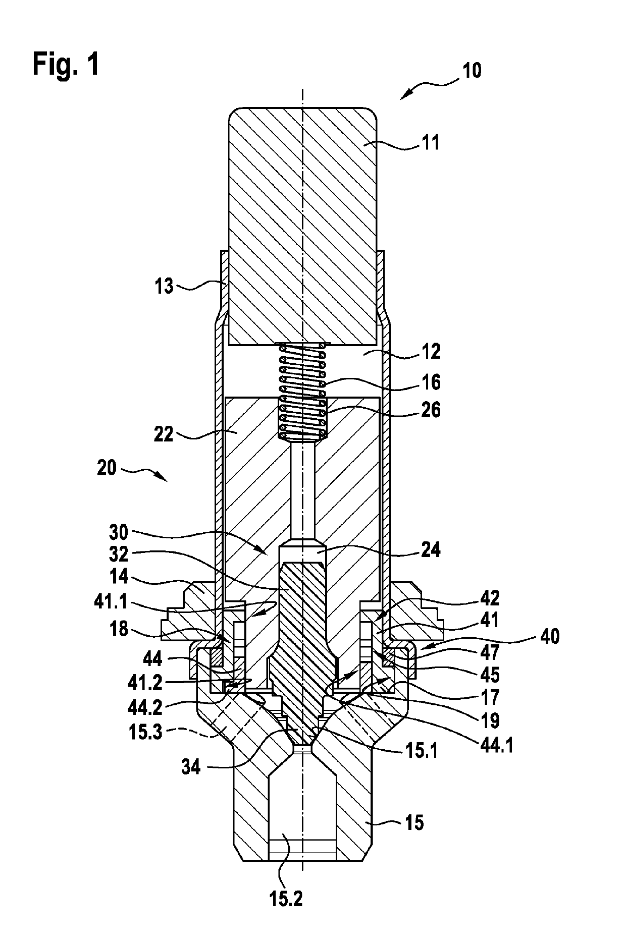
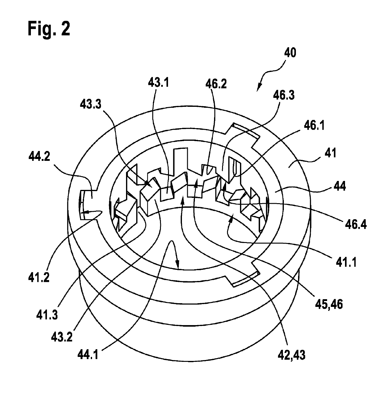
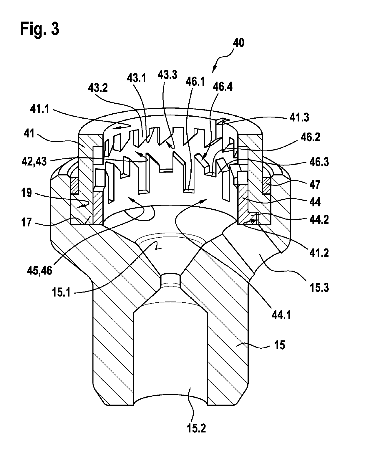
[0024]As can be seen from FIGS. 1 to 11, the illustrated exemplary embodiment of a solenoid valve 10 according to the invention for a hydraulic brake system 1 comprises a solenoid assembly (not illustrated in any more detail), a pole core 11, a guide sleeve 13 connected to the pole core 11, a valve armature 20 which is guided in axially movable fashion within the guide sleeve 13 and which can be driven counter to the force of a resetting spring 16 by a magnet force generated by the solenoid assembly or can be driven by the force of the resetting spring 16 and which axially moves a plunger 30 with a closing element 34, and a valve body 15 which is connected to the guide sleeve 13 and which has a valve seat 15.1 which is arranged between at least one first flow opening 15.2 and at least one second flow opening 15.3, wherein the plunger 30 is fixedly connected to the valve armature 20. Here, the valve body 15 has a receiving region 19 which at least partially receives a guide assembly ...
PUM
 Abstract
Description
Claims
Application Information
 - R&D
- Intellectual Property
- Life Sciences
- Materials
- Tech Scout
- Unparalleled Data Quality
- Higher Quality Content
- 60% Fewer Hallucinations
Browse by: Latest US Patents, China's latest patents, Technical Efficacy Thesaurus, Application Domain, Technology Topic, Popular Technical Reports.
© 2025 PatSnap. All rights reserved.Legal|Privacy policy|Modern Slavery Act Transparency Statement|Sitemap|About US| Contact US: help@patsnap.com


