Automatic Teller Machine (ATM) for Vehicle Driver

a technology for automatic teller machines and vehicle drivers, which is applied in the direction of machine supports, instruments, gearing, etc., can solve the problems of reducing the efficiency requiring a large space for the operation of the automated teller machine, and so on

Active Publication Date: 2010-05-27
NAUTILUS HYOSUNG
View PDF10 Cites 26 Cited by
  • Summary
  • Abstract
  • Description
  • Claims
  • Application Information

AI Technical Summary

Benefits of technology

[0016]As described above, the automated teller machine for a vehicle driver according to the present invention is constructed such that the driver within the vehicle introduced in the financial transaction area can directly adjust the angle of the display unit provided on the front surface of the automated teller machine, whereby the driver within a vehicle can conveniently verify the information, input information, and perform the financial transaction. Simultaneously, the present invention has the advantageous effects in that it is possible to install the automated teller machine in a narrow space and to save the maintenance cost due to the low power consumption.
in that it is possible to install the automated teller machine in a narrow space and to save the maintenance cost due to the low power consumption.

Problems solved by technology

In these structures, since the main body of the automated teller machine, which has a large volume, is directly moved to the driver, a large space is required for operating the automated teller machine.
As such, the power consumption is so high that the efficiency of the automated teller machine is lowered.
In addition, the driver waits until the main body is moved and approaches to the vehicle, and then performs the financial transaction, so that there is a problem in that the financial transaction is temporally delayed more or less.
Also, since the main body is directly moved in the forward and backward directions in a vehicle passage, the main body may cause an accident with the vehicle and influence detrimentally a safety of the vehicle driver.

Method used


Image

  • Automatic Teller Machine (ATM) for Vehicle Driver
  • Automatic Teller Machine (ATM) for Vehicle Driver
  • Automatic Teller Machine (ATM) for Vehicle Driver

Examples


first embodiment

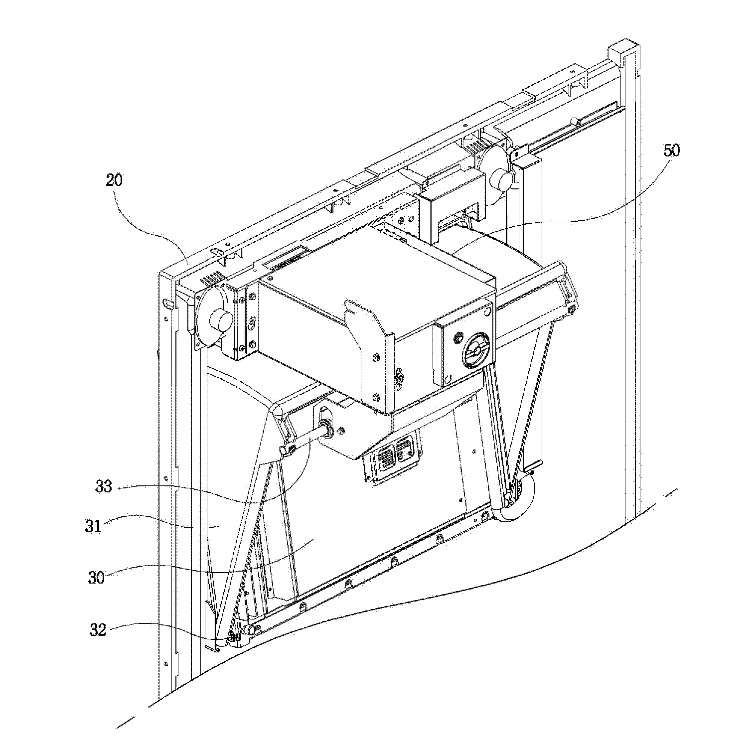
[0029]Referring to FIG. 3 and FIG. 4, the automated teller machine according to the present invention comprises a main body 10 installed in a financial service area, a panel unit 20 provided on a front surface of the main body 10 to be provided with a financial transaction means, a display unit 30 provided at one side of the panel unit 20 to be rotatable frontward and rearward, a manual button unit 40 provided at a predetermined location of the panel unit 20 to receive a rotational angle of the display unit 30 from the vehicle driver, and a control unit 50 provided in the main body to control the rotational angle of the display unit through a signal transmitted from the manual button unit 40.

[0030]The main body 10 forms an external appearance of the automated teller machine and installed in the financial service area at which the vehicle driver conducts a financial transaction.

[0031]The panel unit 20 is provided at an upper portion of the main body so that the panel unit 20 is provi...

second embodiment

[0063]FIG. 9 is a view showing a configuration and usage state of an automated teller machine for a vehicle driver according to the present invention.

[0064]Referring to FIG. 9, an automated teller machine 200 for a vehicle driver according to the second embodiment of the present invention comprises a main body 110 installed in a financial service area, a panel unit 120 provided on a front surface of the main body 110 to be provided with a financial transaction means, a display unit 130 provided at one side of the panel unit 120 to be rotatable frontward and rearward, a sensing unit 140 provided at the main body 110 to recognize the height of a vehicle, and a control unit 50 for controlling a rotational angle of the display unit 130 through a signal transmitted from the sensing unit 140.

[0065]Here, a configuration and operation of each of the main body 110, the panel unit 120, the display unit 130 and the control unit 150 of the automated teller machine 200 for a vehicle driver accor...

third embodiment

[0069]FIG. 10 is a view showing a configuration and usage state of an automated teller machine for a vehicle driver according to the present invention.

[0070]Referring to FIG. 10, an automated teller machine 300 for a vehicle driver according to the third embodiment of the present invention comprises a main body 210 installed in a financial service area, a panel unit 220 provided on a front surface of the main body 210 to be provided with a financial transaction means, a display unit 230 provided at one side of the panel unit 220 to be rotatable frontward and rearward, a sensing unit 240 provided at a front surface of the main body 210 to recognize whether a vehicle is introduced in front of the main body; and a control unit (not shown) for controlling a rotational angle of the display unit 230 through a signal transmitted from the sensing unit 240.

[0071]Here, a configuration and operation of each of the main body 210, the panel unit 220, the display unit 230 and the control unit (no...


PUM


Abstract

The present invention relates to an automated teller machine for a vehicle driver, and more particularly, to an automated teller machine for a vehicle driver in which a display unit itself of the automated teller machine is configured to be rotatable so that the vehicle driver may manipulate the display unit conveniently, whereby the vehicle driver can easily verify the data displayed on the display unit and input the information as necessary. The automated teller machine for a vehicle driver according to the present invention comprises a main body installed in a financial service area; a panel unit provided on a front surface of the main body to be provided with a financial transaction means; a display unit provided at one side of the panel unit, the display unit being configured to be rotatable frontward and rearward; a manual button unit provided at a predetermined location of the panel unit to receive a rotational angle of the display unit from a vehicle driver; and a control unit for controlling the rotational angle of the display unit through a signal transmitted from the manual button unit.

Description

BACKGROUND OF THE INVENTION[0001]1. Field of the Invention[0002]The present invention relates to an automated teller machine for a vehicle driver, and more particularly, to an automated teller machine for a vehicle driver in which a display unit itself of the automated teller machine is configured to be rotatable so that the vehicle driver may manipulate the display unit conveniently, whereby the vehicle driver can easily verify the data displayed on the display unit and input the information as necessary while the vehicle driver remains in a vehicle.[0003]2. Description of the Related Art[0004]An automated teller machine (ATM) is an automated machine which can assist basic financial services such as deposit or withdrawal without any bank clerk regardless of time and place in relation to financial services. The automated teller machine is constructed such that a customer can directly perform financial transactions such as deposit and withdrawal with a medium such as an ATM card or a...

Claims


Application Information

Patent Timeline
Patent Type & Authority Applications(United States)
IPC IPC(8): G07F19/00F16H25/20
CPCG07F19/20G07F19/205Y10S248/923Y10T74/18576Y10S902/30Y10S902/33Y10S902/21G07F19/00
Inventor OH, KYOUNG SUCK
Owner NAUTILUS HYOSUNG
Why Eureka
Try Eureka