Pump dispenser

a dispenser and pump technology, applied in the field of pump dispensers, can solve the problems of liquid leakage, easy deformation of the cross section of the cylinder, etc., and achieve the effects of reducing the amount of resin serving as a material, preventing deformation (bending, cross sectional deformation) of the cylinder, and reducing the cos

Inactive Publication Date: 2010-05-27
CANYON
View PDF9 Cites 5 Cited by
  • Summary
  • Abstract
  • Description
  • Claims
  • Application Information

AI Technical Summary

Benefits of technology

[0024]According to the present invention, since the thickness of the cylinder is reduced, the amount of resin serving as a material is reduced, and cost is also reduced.
[0025]Moreover, the “liquid leakage” and “air inclusion” phenomena do not occur.
[0026]Many ribs are formed on the outer wall of the cylinder along the axial direction. Therefore, deformation (bending, cross sectional deformation) of the cylinder is prevented.
[0027]The diameter of the receiver washer supporting the spring body is equal to the diameter of the cylinder. Therefore, deformation (bending, cross sectional deformation) of the cylinder is similarly prevented.
[0028]The lower tongue portion of the piston is formed to be longer than the upper tongue portion. Therefore, even when the cross section of the cylinder is deformed, the lower tongue portion is deformed along the inner wall surface of the cylinder so as to reliably achieve sealing.
[0029]Hereinafter, best modes for carrying out the present invention will be explained based on drawings.

Problems solved by technology

On the other hand, when the thickness of the cylinder is reduced, deformation is readily caused in the cross section of the cylinder.
Therefore, there are drawbacks that “liquid leakage” or “air inclusion” occurs between the cylinder and the piston.
However, under present circumstances, empirically, the wall of the cylinder is caused to have a thickness of 1.5 mm or more by excessively using the total resin amount of the material in order to avoid the above described problems.

Method used


Image

  • Pump dispenser
  • Pump dispenser
  • Pump dispenser

Examples


Embodiment Construction

[0029]Hereinafter, best modes for carrying out the present invention will be explained based on drawings.

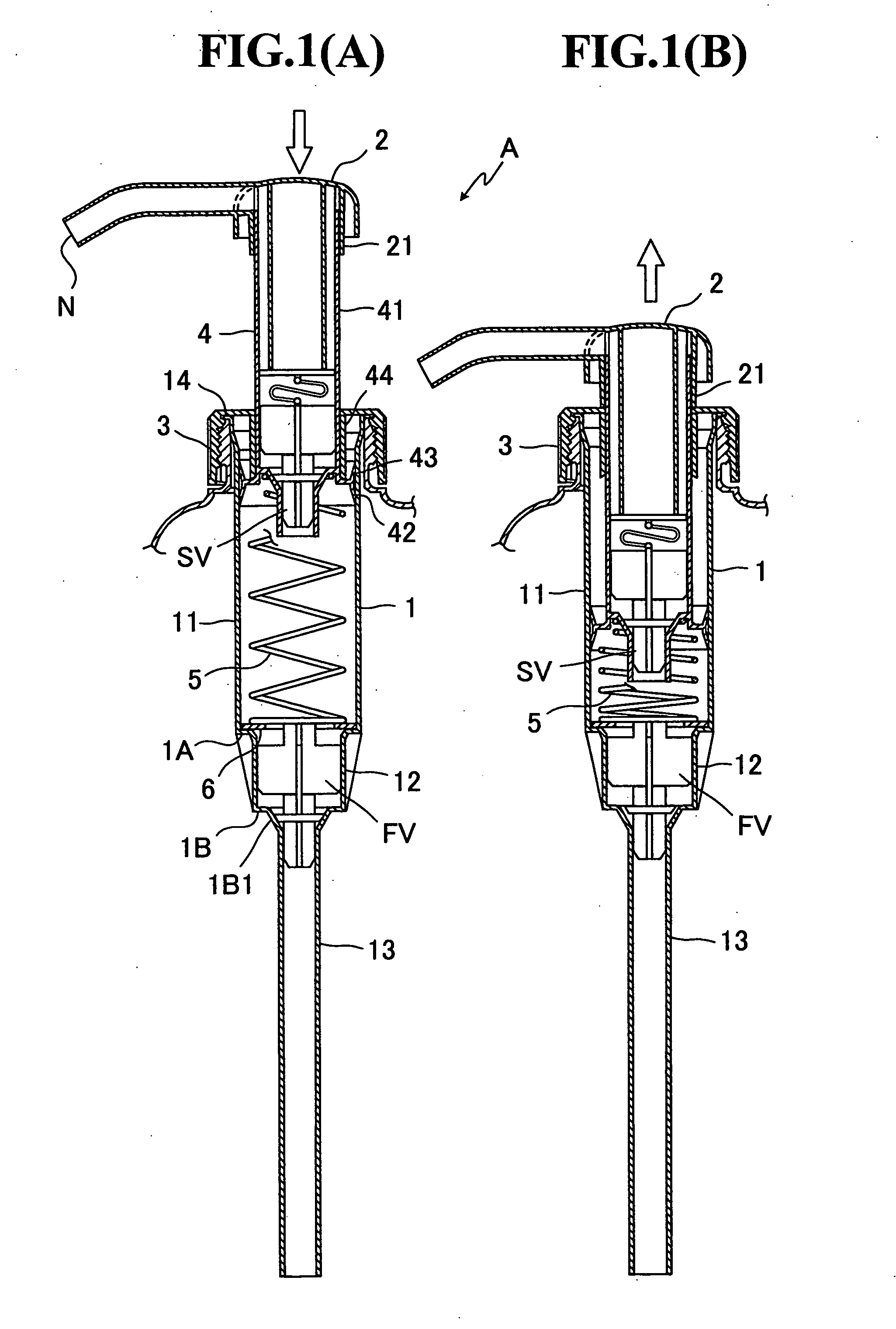
[0030]FIG. 1 is a cross sectional view showing a pump dispenser according to an embodiment of the present invention, wherein (A) shows a state before a nozzle head 2 is pushed down, and (B) shows a state after the nozzle head 2 is pushed down.

[0031]Note that, when liquid is to be discharged from an opening of the nozzle head 2, the above described states of (A) and (B) are repeated.

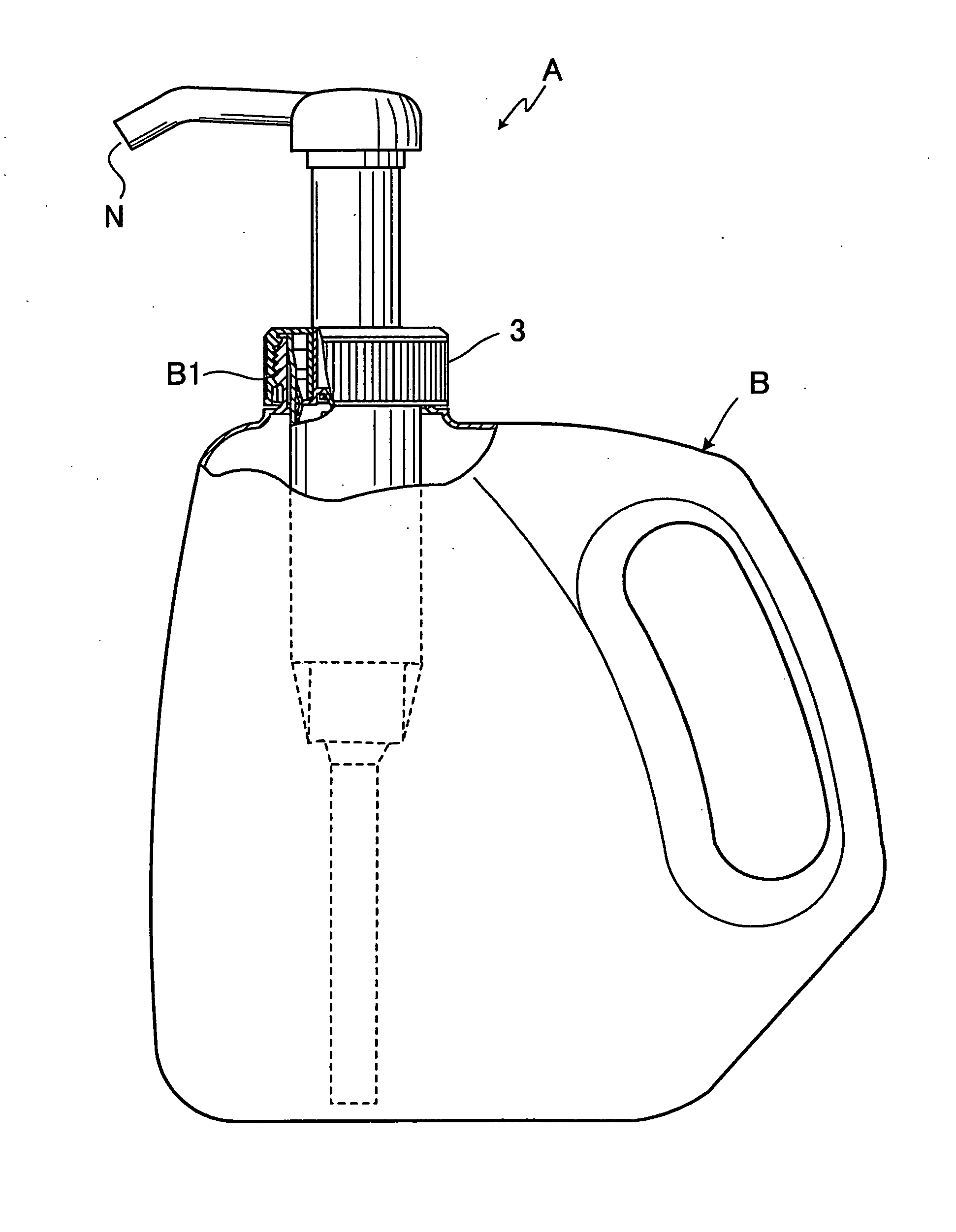
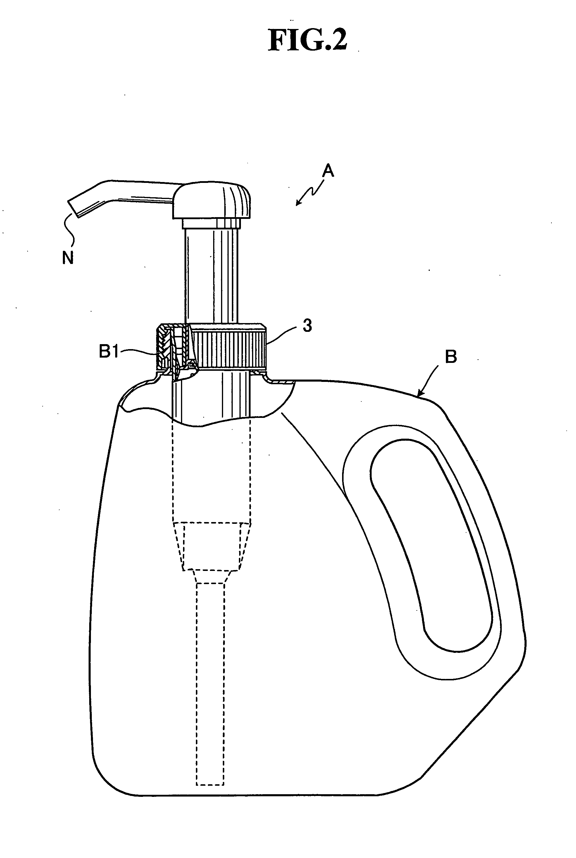
[0032]The pump dispenser A has a cylinder 1 and a cap 3 for attaching the cylinder 1 to a container B.

[0033]Therefore, the pump dispenser A can be readily integrated with the container B by, for example, screwing the cap 3 to an opening B1 of the container (see FIG. 2).

[0034]Moreover, the pump dispenser A has a piston 4, which is slidably attached to the cylinder 1 from inside, and the nozzle head 2, which is coupled to the piston 4.

[0035]Note that a flange portion 14 at the upper end of the cylinder 1...


PUM


Abstract

A push-type dispenser which has a cylinder as thin as possible and is free from deformation is provided. A pump dispenser (A) has a cylinder (1), a piston (4) slidably attached to the cylinder (1) from inside, and a nozzle head (2) having a nozzle opening (N) coupled to the piston (4). The pump dispenser discharges liquid from the nozzle opening (N) by applying a pressure to the liquid filling the interior of the cylinder (1) by pushing the nozzle head (2), wherein the wall of the cylinder has a thickness of 0.6 mm to 1.3 mm.

Description

TECHNICAL FIELD[0001]The present invention relates a pump dispenser which discharges a certain amount of liquid, which is in a container.[0002]Particularly, the present invention relates to a push-type dispenser which has a cylinder having a thickness as thin as possible and is free from deformation.BACKGROUND ART[0003]Conventionally, a pump-equipped container has been used for discharging a certain amount of liquid such as a detergent, medicinal agent, etc.[0004]The pump-equipped container is provided with a discharge mechanism, i.e., a pump dispenser, and, as an example thereof, a push-type pump dispenser, etc. are widely known (see Patent Document 1).[0005]In this dispenser, when a piston is pushed down, a pressure is applied to the liquid which is sucked up into a cylinder via a suction tube, and the liquid is discharged from an opening of a nozzle head.[0006]However, the cylinder, which is integrally formed with the suction tube, is preferred to have a smaller total amount of r...

Claims


Application Information

Patent Timeline
Patent Type & Authority Applications(United States)
IPC IPC(8): G01F11/00B65D88/54
CPCB05B11/3001B05B15/005B05B11/3073B05B15/30B05B15/63B05B11/1001B05B11/1073
Inventor TADA, TETSUYA
Owner CANYON
Why Eureka
Try Eureka