Battery system with relays

a battery system and relay technology, applied in battery/fuel cell control arrangement, safety/protection circuit, cell components, etc., to achieve the effect of reliably cutting off excessive battery current, and reliable cutting o

Active Publication Date: 2010-05-27
SANYO ELECTRIC CO LTD
View PDF4 Cites 95 Cited by
  • Summary
  • Abstract
  • Description
  • Claims
  • Application Information

AI Technical Summary

Benefits of technology

[0010]The battery system described above has the characteristic that the relays can reliably cut-off excessive battery current without fusing relay contacts together, and excessive battery current can also be reliably cut-off by the fuse. This is because the battery system described above establishes a delay time between excessive battery current detection and ON to OFF switching of the relays. Further, for this delay time, the fusing current of the fuse is set below the maximum relay cut-off current and above the maximum allowable battery charging and discharging current. When excessive current greater than the maximum cut-off current of the relays flows through the battery of this battery system, the fuse is blown to cut-off current during the delay time, and the relays are switched OFF for cut-off when the delay time has elapsed. Therefore, excessive battery current can be reliably and safely cut-off by both the fuse and the relays without fusing relay contacts together. Conversely, if excessive current flow continues longer than the delay time, the current is lower than the current required to blow the fuse, and must be lower than the maximum cut-off current of the relays. Consequently, it is possible for the relays to cut-off current without fusing contacts together.

Problems solved by technology

This is because the battery system described above establishes a delay time between excessive battery current detection and ON to OFF switching of the relays.

Method used


Image

  • Battery system with relays
  • Battery system with relays
  • Battery system with relays

Examples


Embodiment Construction

)

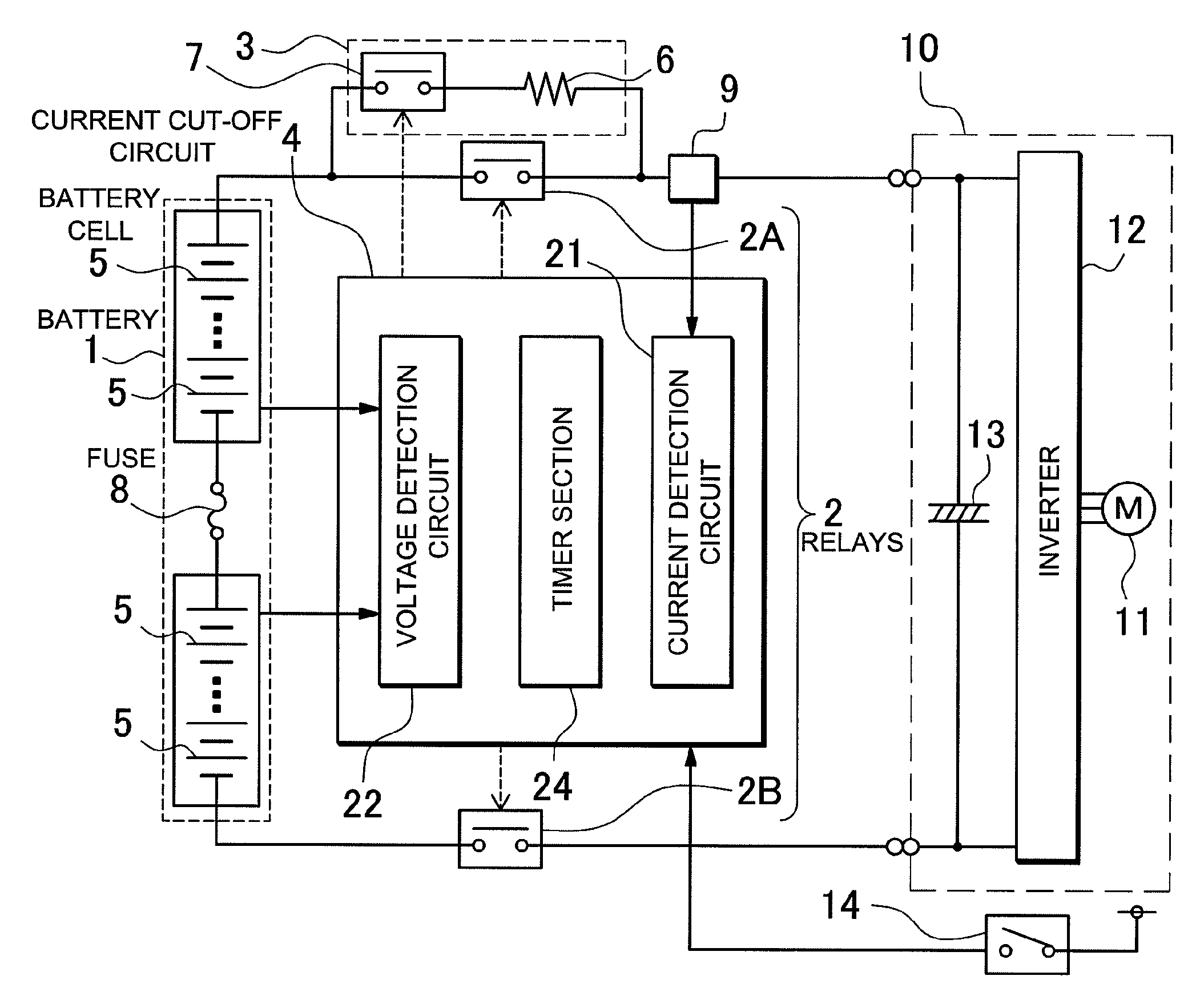
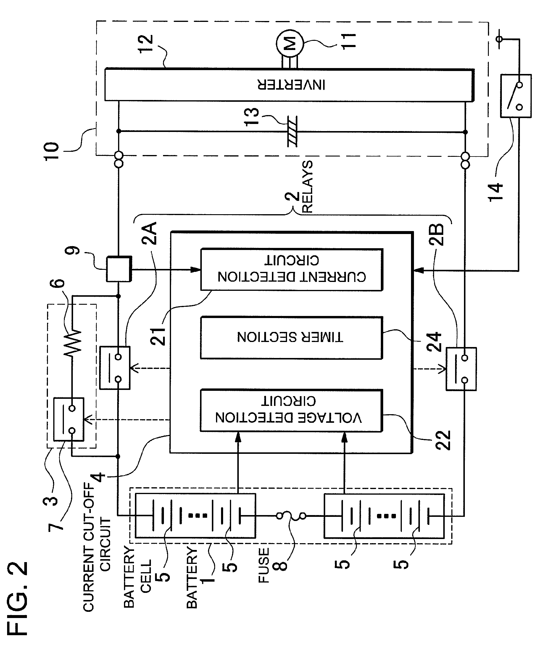
[0015]Another battery system is provided with a battery 1 having a plurality of battery cells 5 that can be recharged, a fuse 8 connected in series with the battery 1 that is self-fusing with excessive current flow, and internal current cut-off sections established in the battery cells 5 that cut-off battery cell 5 internal circuit connections under excessive current or over-charging conditions. The fusing characteristics of the fuse 8 are set to blow the fuse 8 at a current that is lower than the cut-off current of the internal current cut-off sections. In this battery system, when excessive current flows in the battery 1, the fuse 8 blows before internal current cut-off section activation.

[0016]Still another battery system is provided with a battery 1 having a plurality of battery cells 5 that can be recharged, relays 2 connected in series with the output-side of the battery 1, a current cut-off circuit 4 that detects excessive battery 1 current and controls the relays 2 from ON ...


PUM

PropertyMeasurementUnit
output voltageaaaaaaaaaa
currentaaaaaaaaaa
output voltageaaaaaaaaaa

Abstract

The battery system is provided with a battery 1 that can be recharged, a fuse 8 connected to the battery 1 that blows with excessive current flow, relays 2 connected to the output-side of the battery 1, and a current cut-off circuit 4 that detects excessive battery 1 current and controls the relays 2. The current cut-off circuit 4 detects excessive battery 1 current, and is provided with a timer section 24 that designates a time delay until the relays 2 are switched from ON to OFF. For the delay time of the timer section 24, the fusing current of the fuse 8 is set lower than the maximum cut-off current of the relays 2 and higher than the maximum allowable battery 1 charging and discharging current. In a situation where excessive current greater than the maximum cut-off current of the relays 2 flows through the battery 1, the fuse 8 is blown during the timer 24 delay time, and the current cut-off circuit 4 switches the relays 2 from ON to OFF when the delay time has elapsed.

Description

BACKGROUND OF THE INVENTION[0001]1. Field of the Invention[0002]The present invention relates to a battery system optimized for a car power source apparatus that supplies electric power to a motor that drives the vehicle, and in particular to a battery system that detects excessive current and cuts-off current flow with a fuse and relays.[0003]2. Description of the Related Art[0004]A battery system has been developed with a series connected fuse and relays to prevent excessive battery current. (Refer to Japanese Patent Application Disclosure 2008-193776.) As shown in FIG. 1, the battery system of Japanese Patent Application 2008-193776 has a battery 91 divided into two battery blocks 95, and those battery blocks 95 are connected in series via a fuse 98. In addition, the battery system has relays 92 connected to the output-side of the battery 91. In this battery system, if excessive current flows in the driving battery, the fuse 98 blows and cuts-off battery 91 current. Furthermore, ...

Claims


Application Information

Patent Timeline
Patent Type & Authority Applications(United States)
IPC IPC(8): H02J7/00H01M50/583H01M50/588H01M50/59
CPCB60L3/0046H02H9/001H02J7/0026Y02T10/7055Y02T90/34B60L2240/549B60L2240/80B60L2270/20B60L3/0069B60L3/04B60L11/1803B60L11/1862B60L11/1864B60L2240/547Y02T10/7044Y02T10/7005Y02T10/7061Y02T10/7011B60L3/0053B60L50/51B60L58/21B60L58/15B60L58/18H02J7/0014Y02T10/70H02J7/00302H02J7/00304H02H7/18H01H85/46Y02T90/40
Inventor FURUKAWA, KIMIHIKOYANO, JUNYATANAKA, KUNIHO
Owner SANYO ELECTRIC CO LTD
Why Eureka
Try Eureka