Hoisting machine

a technology of hoisting machine and control box, which is applied in the direction of hoisting equipment, motor/generator/converter stopper, dynamo-electric converter control, etc., can solve the problems of inability to achieve the effect of promoting heat dissipation

Active Publication Date: 2010-05-27
KITO CORP
View PDF6 Cites 9 Cited by
  • Summary
  • Abstract
  • Description
  • Claims
  • Application Information

AI Technical Summary

Benefits of technology

[0011]Thus, the hoisting machine is provided with a heat dissipation means that dissipates heat generated from the inverter to the speed reduction mechanism casing. Therefore, heat generated from the inverter can be efficiently dissipated to the surrounding air through the speed reduction mechanism casing having a large heat capacity. Further, because the interior of the speed reduction mechanism casing is an oil bath containing a lubricating oil, it is possible to expect cooling of the inverter by oil cooling. Accordingly, the inverter can be efficiently cooled, and the hoisting machine can be operated at high frequency.
[0056]The hoisting machine according to the present invention uses, as a regenerative braking resistor, a resistor in which resistance elements are disposed in concave spaces at the reverse side of a corrugated metal plate constituting a resistor casing and an insulating material is filled in the space between the corrugated metal plate and the associated flat metal plate, including the concave spaces at the reverse side of the corrugated metal plate. Thus, the corrugated metal plate provides a wide surface area, and the corrugated metal plate surface having a wide area serves as a heat dissipation surface. Therefore, heat from the resistance elements can be dissipated effectively. Accordingly, heat from the regenerative braking resistor can be efficiently dissipated in addition to the advantage that heat from the inverter can be efficiently dissipated as stated above. Thus, the invention of this application can provide an inverter-incorporating hoisting machine capable of performing high-frequency operation.

Problems solved by technology

When a hoisting machine is operated at high frequency, i.e. when the operating time of the hoisting machine accounts for 60% or more of the sum total (100%) of the operating time and down time, a large amount of heat is generated from the inverter, and the heat undesirably stays in a control box housing the inverter.
Because the panel 101 is made of steel, it is inferior in thermal conductivity to aluminum or other similar material.
The panel 101 is also inferior in heat dissipation properties because it is thin in thickness.
Therefore, the heat generated from the inverter 102 cannot escape but undesirably stays in the control box 100, causing the temperature to rise.
With this structure, however, wiring and maintenance are troublesome because the components other than the inverter 102, i.e. the electromagnetic switch 103 and the transformer 104, are attached to the main body side of the hoisting machine through the panel 101.
Further, there is a fear that a possible impact on the control box 100 will be applied directly to the inverter 102.
In such a case, it takes time and labor to wire and install the resistors 110.
With this method, however, the resistance elements 112 radiate heat toward each other and thus release a large amount of heat.
Thus, the method is inferior in heat dissipation properties.
This method suffers, however, from the problem that there is an increase in the dimensions of the resistor 110 including the heatsink 120, particularly the height dimension.
In addition, if the condition of contact between the heatsink 120 and the resistor 110 is not satisfactory, the heat dissipation properties degrade.
Further, the use of the heatsink 120 increases the number of component parts correspondingly and causes an increase in cost.

Method used


Image

  • Hoisting machine
  • Hoisting machine
  • Hoisting machine

Examples


Embodiment Construction

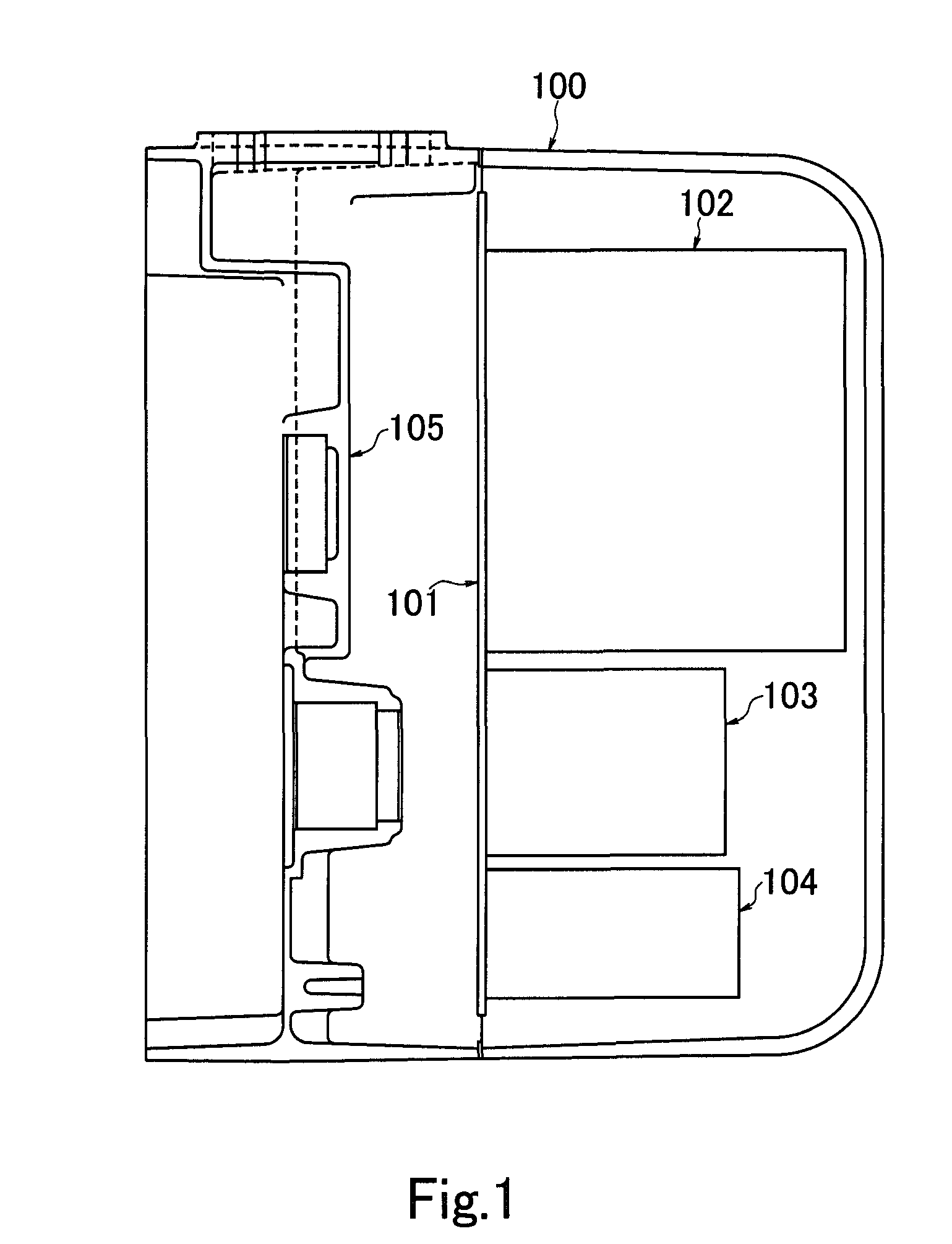
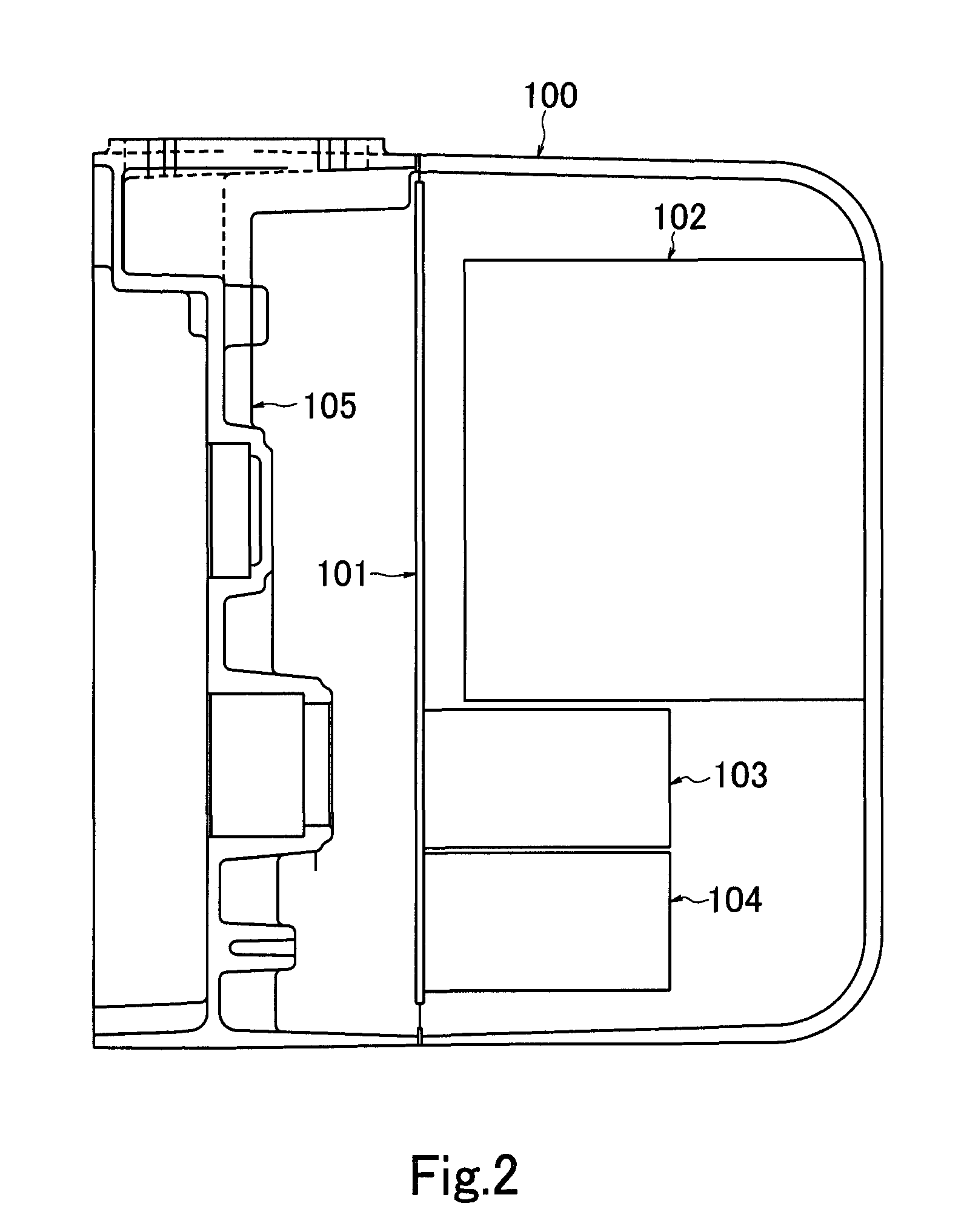
[0034]An embodiment of the present invention will be explained below with reference to the accompanying drawings. FIG. 5 is a sectional plan view showing an example of the internal structure of a control box of an electric chain block according to the present invention. As illustrated in the figure, an inverter 12 is attached directly to a speed reduction mechanism casing 15. In this regard, the inverter 12 and the speed reduction mechanism casing 15 have respective contact surfaces that are flat relative to each other so as to be attached in close contact (surface contact) with each other. The speed reduction mechanism casing 15 is formed by aluminum die casting and contains a lubricating oil (not shown) for lubricating gears and so forth (not shown) constituting a speed reduction mechanism.

[0035]In a control box 10 are disposed an electromagnetic switch 13 and a transformer 14 that are mounted on a steel panel 11. When the electric chain block is operated at high frequency, a larg...


PUM


Abstract

A hoisting machine is provided that is capable of efficiently dissipating heat generated from an inverter incorporated in the hoisting machine main body into the surrounding air with a simple structure and hence capable of performing high-frequency operation.A hoisting machine having a load hoisting motor and a speed reduction mechanism and driving the load hoisting motor with an inverter 12 incorporated in the hoisting machine main body is provided with a heat dissipation means that dissipates heat generated from the inverter 12 to a speed reduction mechanism casing 15 that houses the speed reduction mechanism. The heat dissipation means is a means for attaching the inverter 12 directly to the speed reduction mechanism casing 15 in close contact therewith through surface contact at least a part of the inverter 12.

Description

TECHNICAL FIELD[0001]The present invention relates to hoisting machines, such as electric chain blocks and electric hoists, which drive a load hoisting motor with an inverter incorporated therein. More particularly, the present invention relates to a hoisting machine capable of efficiently dissipating heat generated from the inverter into the surrounding air and also capable of efficiently dissipating, into the surrounding air, heat generated from a regenerative braking resistor when supplied with a regenerative electric current generated during regenerative braking of the load hoisting motor, and hence capable of performing high-frequency operation.BACKGROUND ART[0002]There are hoisting machines, such as electric chain blocks and electric hoists, which use as a load hoisting motor an inverter-driven motor that is driven by an inverter incorporated in the hoisting machine main body. In such a hoisting machine, when the temperature of the inverter exceeds a predetermined set temperat...

Claims


Application Information

Patent Timeline
Patent Type & Authority Applications(United States)
IPC IPC(8): H01C1/08
CPCB66D3/20B66D3/22B66D3/26B66D1/12B66D1/28H01C1/08H02P3/18
Inventor ISHIKAWA, KAZUMITSUNISHIKAWA, KAZUHIRO
Owner KITO CORP
Why Eureka
Try Eureka