Patch antenna with metal walls

a patch antenna and metal wall technology, applied in the field of patch antennas, can solve the problems of increasing costs, different outer shapes, and configuration of this invention, and achieve the effects of simple method, reduced radiation opening of the antenna, and broadened directional beam width

Inactive Publication Date: 2010-05-27
NEC CORP
View PDF4 Cites 17 Cited by
  • Summary
  • Abstract
  • Description
  • Claims
  • Application Information

AI Technical Summary

Benefits of technology

[0014]It is an object of the present invention to provide a novel means for enabling a broadening of the directional beam width of a patch antenna by a comparatively simple method.
[0015]The patch antenna for linearly polarized waves of the present invention for achieving the above-described object is provided with a patch antenna element that is formed on a dielectric substrate and that is configured to enable the transmission and reception of linearly polarized waves, and metallic walls that are provided at the periphery of the patch antenna element and that tilt inward to reduce the size of the radiation opening of the antenna.
[0016]The above-described invention is a device in which the shape of the metallic walls is arranged to, for example, tilt inward to reduce the dimension of the radiation opening of the antenna. In this way, the patch antenna for linearly polarized waves of the present invention enables adjustment of both the directional beam width in a plane that is perpendicular to the polarization plane and the directional beam width in a plane that is horizontal to the polarization plane, i.e., enables a broadening of the directional beam width of the patch antenna.

Problems solved by technology

However, adopting separate antennas for vertically polarized waves and horizontally polarized waves typically necessitates the preparation of two types of antennas, and further results in outer shapes that are different and increased costs.
However, the configuration of this invention, in which a rectangular parallelepiped dielectric block is arranged on the radiation surface of an antenna element and a passive element composed of a metallic plate formed in a vertical direction is provided on the front surface, is comparatively complex.

Method used


Image

  • Patch antenna with metal walls
  • Patch antenna with metal walls
  • Patch antenna with metal walls

Examples


first embodiment

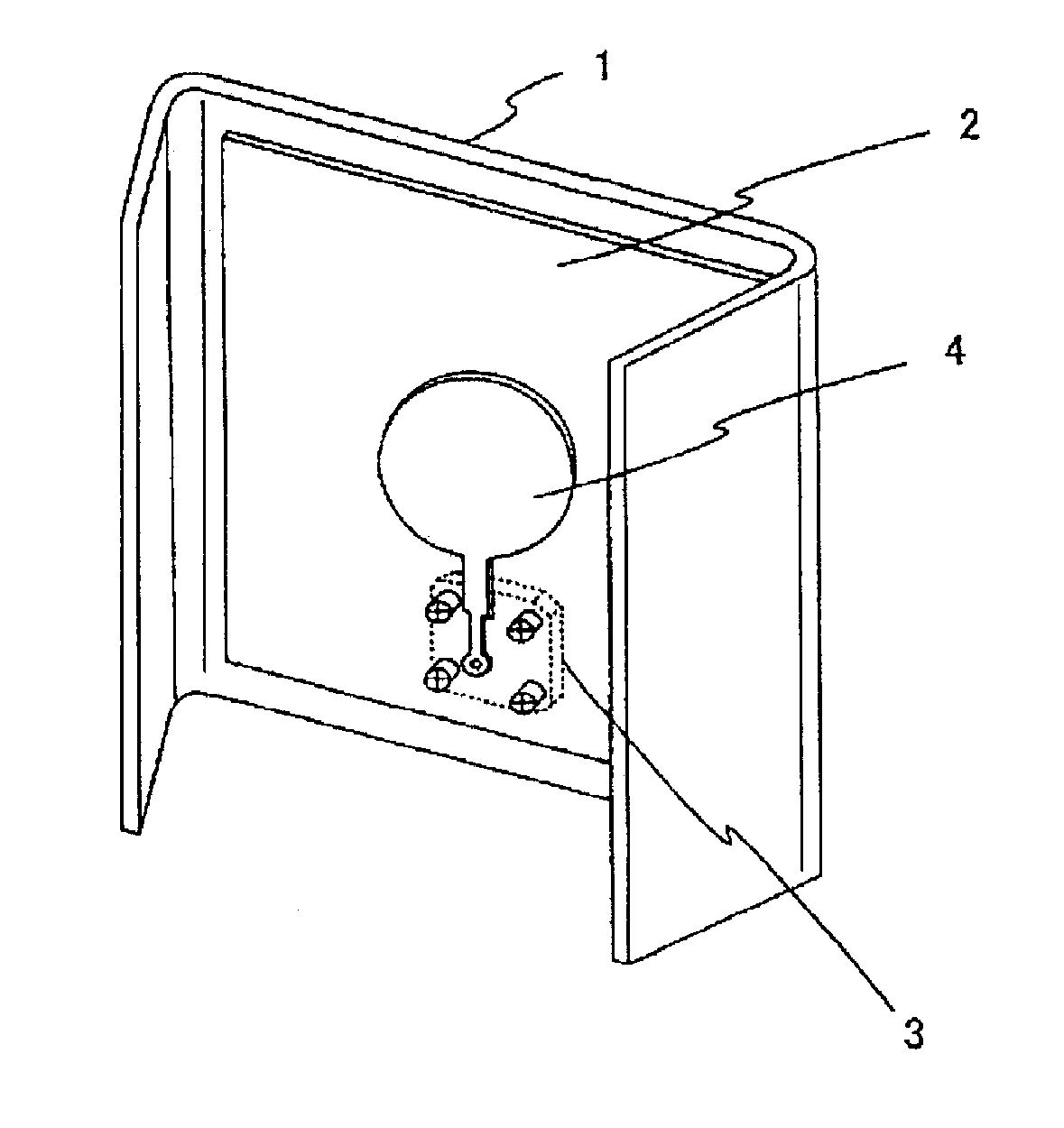
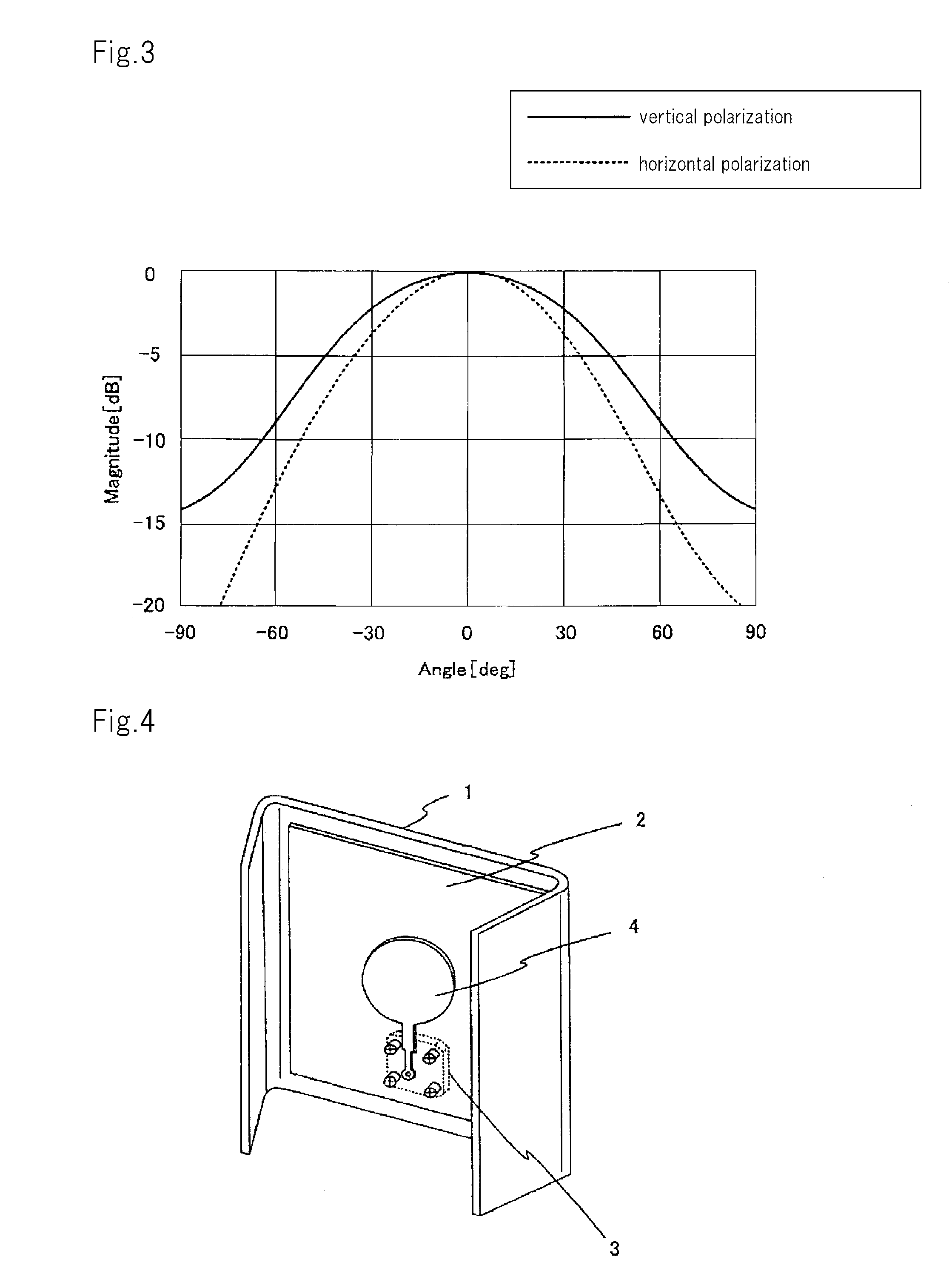
[0051]FIGS. 4 to 6 are a perspective view, front elevation, and side view of a patch antenna that shows the present invention. FIG. 7 shows radiation patterns in the horizontal plane and vertical plane of the patch antenna of the present embodiment. FIG. 8 shows the radiation patterns of the horizontal plane when the patch antenna of the present embodiment is used as a vertical-polarized antenna and when the patch antenna of the present embodiment is used as a horizontal-polarized antenna.

[0052]The patch antenna of the present embodiment is made up of metallic walls 1, patch conductor 4, and coaxial connector 3. Patch conductor 4 is formed in a round shape by, for example, etching on printed board 2, which is a dielectric substrate. This patch conductor 4 is supplied with power by way of coaxial connector 3 from the rear surface of metallic walls 1.

[0053]Metallic walls 1 can be constructed from one substantially rectangular metal plate with the rear surface of printed board 2 adhere...

second embodiment

[0064]FIGS. 13A-13C are a perspective view, a front elevation, and a side view, respectively, of a patch antenna that represents the present invention.

[0065]In the present embodiment, passive element 5 for broadening the band is mounted by way of spacer 6 on the radiation surface of a patch antenna that is formed on printed board 2. The radiation pattern and other effects of the antenna are similar to the first embodiment.

third embodiment

[0066]FIGS. 14A-14C are a perspective view, a front elevation, and a side view, respectively, of a patch antenna that represents the present invention.

[0067]The present embodiment is made up from metallic walls 1, a patch antenna element arranged by, for example, etching on printed board 2, and coaxial connectors 3a and 3b. The patch antenna has a round or square shape formed by the printed board and is supplied from coaxial connectors 3a and 3b by way of the rear surface of metallic walls 1.

[0068]In the present embodiment, connector terminals for vertically polarized waves and horizontally polarized waves are provided to make the patch antenna a dual-polarized antenna. Metallic walls 1 are arranged with an inward inclination such that metallic walls 1 are smaller than the dimension of the radiation opening of the patch antenna as seen from the direction of antenna radiation.


PUM


Abstract

A patch antenna is provided with a metallic wall (1); a patch conductor (4) formed on a printed board (2), i.e., a dielectric substrate, by etching or the like; and a power feeding means for the patch conductor. The metallic wall (1) is bent forward along the both side surfaces of the printed board (2). The metallic wall (1) is inclined inward, and an interval between the both end portions is smaller than a radiation aperture dimension of the patch antenna when viewed from an antenna radiation direction. With such configuration, a directional beam width can be widened, and the directional beam width on a surface parallel to the polarization surface of linearly-polarized wave and the directional beam width on a surface orthogonally intersecting with the polarization surface of the linearly-polarized wave are accorded with each other.

Description

TECHNICAL FIELD[0001]The present invention relates to a patch antenna, and more particularly, relates to a patch antenna chiefly used in a base station of a wireless system that requires a plurality of antenna elements such as diversity and MIMO (Multiple Input Multiple Output).BACKGROUND ART[0002]In systems that employ WiMAX (Worldwide Interoperability for Microwave Access) technology or next-generation portable telephone systems, MIMO technology and diversity technology are frequently used, and smaller antennas and lower costs are in demand. A MIMO system requires a plurality of antennas, and antennas that feature little cross correlation in a small area have therefore become necessary.[0003]To meet this demand, a dual-polarized antenna is sought that can be used for both a vertically polarized wave and a horizontally polarized wave. Further, an antenna configuration is sought in which the directional beam width matches vertically polarized waves and horizontally polarized waves s...

Claims


Application Information

Patent Timeline
Patent Type & Authority Applications(United States)
IPC IPC(8): H01Q1/38
CPCH01Q19/106H01Q9/0407H01Q1/246
Inventor YUSA, HIROYUKI
Owner NEC CORP
Why Eureka
Try Eureka