Imaging apparatus and its drive controlling method

a technology of drive control and imaging apparatus, which is applied in the direction of exposure control, instruments, television systems, etc., can solve the problems of inability to achieve a long exposure time shorter than this limit and the accuracy limit of the mechanical shutter, and achieve the effect of less influenced by smears

Inactive Publication Date: 2010-05-27
FUJIFILM CORP
View PDF5 Cites 14 Cited by
  • Summary
  • Abstract
  • Description
  • Claims
  • Application Information

AI Technical Summary

Benefits of technology

[0015]In accordance with the above configuration and method, a high-quality image which is less in

Problems solved by technology

However, the mechanical shutter has a limit in accuracy because it is mechanica

Method used


Image

  • Imaging apparatus and its drive controlling method
  • Imaging apparatus and its drive controlling method
  • Imaging apparatus and its drive controlling method

Examples


Embodiment Construction

[0024]Now referring to the drawings, embodiments of the invention will be described below.

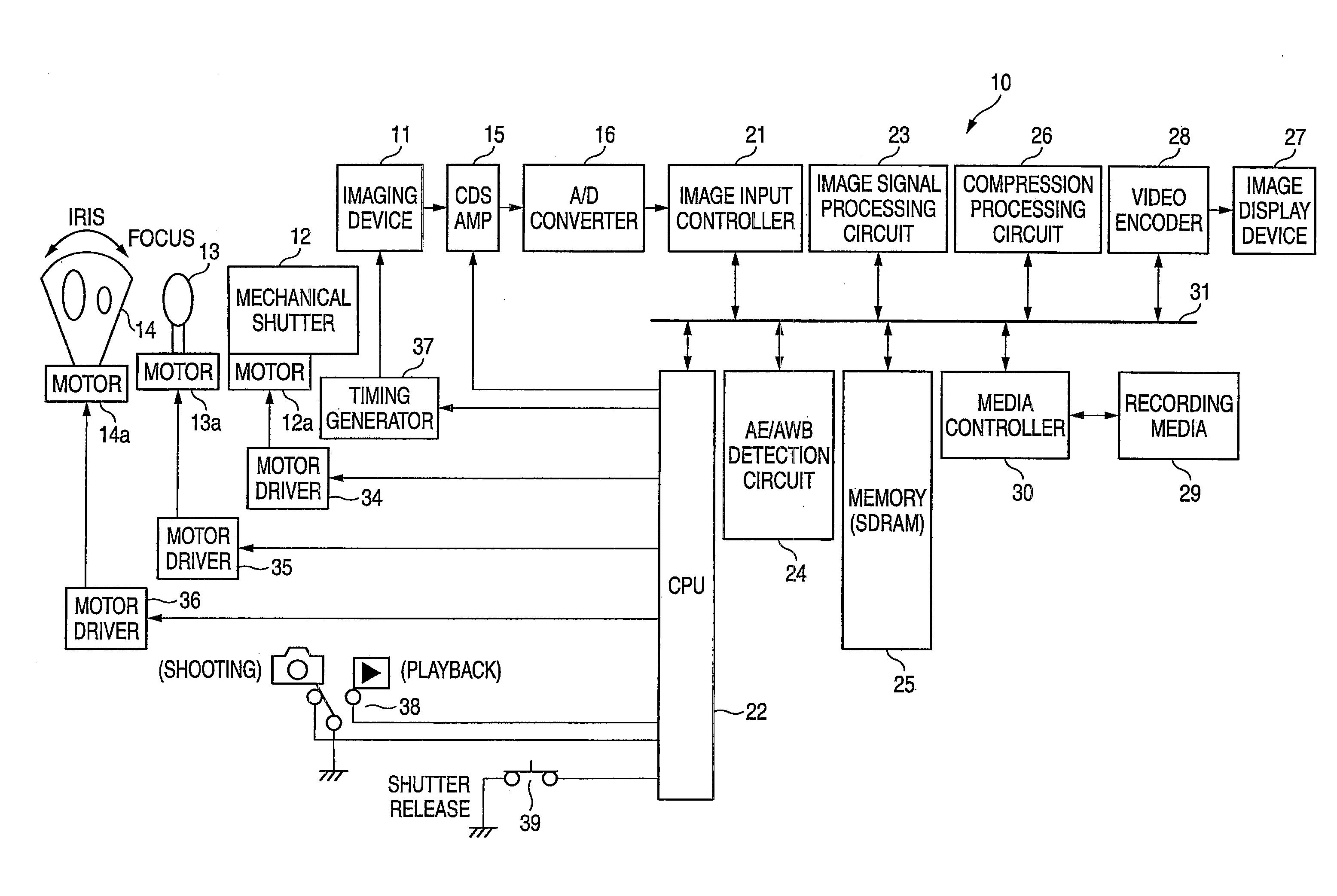
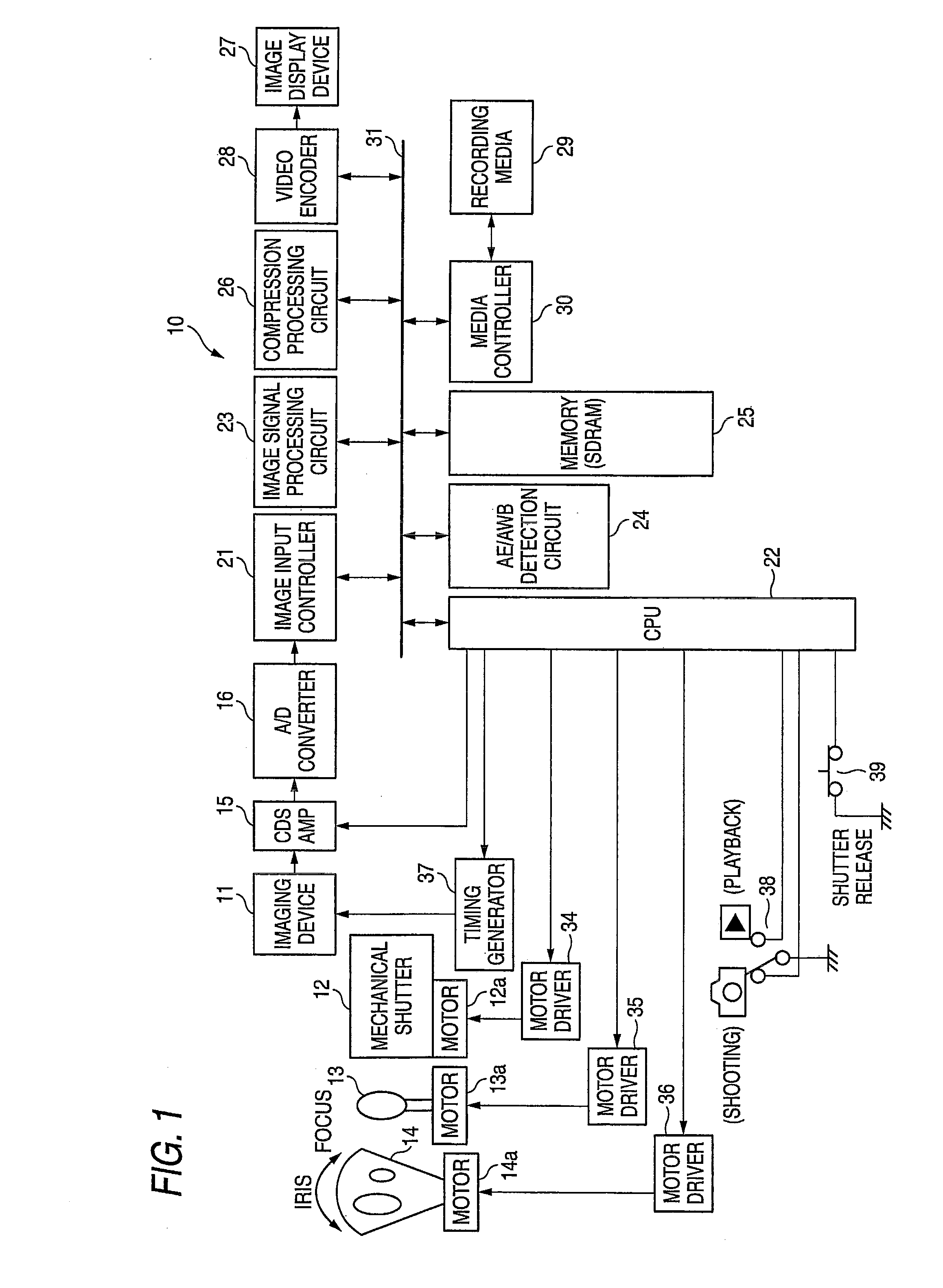
[0025]FIG. 1 is a block diagram of an imaging apparatus according to one embodiment. This imaging apparatus (in this embodiment, a digital still camera) 10 includes a CCD-type solid-state imaging device 11, a mechanical shutter 12 which is provided ahead of the solid-state imaging device 11, an imaging lens 13, an diaphragm (iris) 14, a CDSAMP (correlated double sampling (CDS), a gain control amplifier (AMP)) 15 which performs analog signal processing for an output signal (taken image signal) from the imaging device 11 and an analog / digital (A / D) converter 16 which converts an output signal from the CDSAMP 15 into a digital signal.

[0026]The imaging apparatus 10 further includes an image input controller 21, a central processing unit (CPU) 22, an image signal processing circuit 23, an AE / AWB detection circuit 24, an SDRAM 25, a compression processing circuit 26, a video encoder 28, a media contr...


PUM


Abstract

An imaging apparatus includes a solid-state imaging device and an imaging device driver. The imaging device includes first pixels and second pixels. The first pixels execute an imaging operation for a long exposure time. The second pixels execute an imaging operation for a short exposure time which overlaps with a part of the long exposure time. The first and second pixels are mixedly arranged in a two dimensional array. Plural different drive controlling modes each controlling operation timings of start and end of exposure of the first pixels and operation timings of start and end of exposure of the second pixels are prepared in advance. The imaging device driver selects one of the drive controlling modes in accordance with a shooting condition under which an object image is taken and drives the solid-state imaging device in accordance with the selected mode.

Description

CROSS-REFERENCE TO RELATED APPLICATIONS[0001]This application claims the benefit of Japanese Patent Application No. 2008-302780, filed Nov. 27, 2008, the entire contents of which are hereby incorporated by reference, the same as if set forth at length.BACKGROUND[0002]1. Technical Field[0003]The invention relates to an imaging apparatus capable of taking an object image with a wide dynamic range and its drive controlling method.[0004]2. Related Art[0005]JP 2003-219281 A describes an imaging apparatus that can take an object image with a wide dynamic range. This imaging apparatus includes a CCD-type solid-state imaging device to execute short-exposure-time imaging using all pixels and subsequently execute long-exposure-time imaging using all the pixels so that image data obtained by both imaging processes are combined, to thereby extend the dynamic range of the object image.[0006]However, in this imaging apparatus, the short-exposure-time imaging and the long-exposure-time imaging don...

Claims


Application Information

Patent Timeline
IPC IPC(8): H04N5/335H04N5/235H04N5/353H04N5/355H04N5/359H04N5/372
CPCH04N9/045H04N5/35563H04N25/585H04N25/134
Inventor YAMASHITA, HAYATO
Owner FUJIFILM CORP
Why Eureka
Try Eureka