Multi-step transmission

a transmission and multi-step technology, applied in fluid gearings, transportation and packaging, gearing, etc., can solve the problems of high structural cost and complexity, and achieve the effects of reducing structural space required, improving efficiency in high gears, and optimizing structural complexity

Inactive Publication Date: 2010-05-27
ZF FRIEDRICHSHAFEN AG
View PDF17 Cites 21 Cited by
  • Summary
  • Abstract
  • Description
  • Claims
  • Application Information

AI Technical Summary

Benefits of technology

[0014]The purpose of the present invention is to propose a multi-step transmission of the type mentioned above, in which the structural complexity is optimized, the structural space required is reduced, and in addition the efficiency in high gears is improved in relation to drag and gearing losses. Moreover, in the multi-step transmission according to the invention low torques should act upon the shift elements and planetary gearsets, and the rotational speeds of shafts, shift elements and planetary gearsets should be kept as low as possible. Finally, the transmission according to the invention should be suitable for any mounting configuration in a vehicle, in particular for a front-transverse arrangement.
[0018]Owing to the design of the multi-step transmission according to the invention, transmission ratios particularly suitable for passenger vehicles are obtained, along with a considerable increase in the overall spread of the multi-step transmission, whereby the driving comfort is improved and the fuel consumption is significantly reduced.
[0020]Moreover, with the multi-step transmission according to the invention the efficiency in high gears is good in relation to drag and gearing losses.
[0021]Furthermore, the torques acting on the shift elements and planetary gearsets of the multi-step transmission are low, which reduces wear in the multi-step transmission in an advantageous manner. Besides, since the torques are low the size of components can be correspondingly smaller, and this reduces the structural space occupied and the corresponding costs. In addition, the rotational speeds of shafts, shift elements and planetary gearsets are low.

Problems solved by technology

In addition, these transmissions should not be characterized by high structural cost and complexity, in particular having a small number of shift elements and avoiding double shifts during sequential shifting processes, so that for shifts in defined gear groups in each case only one shift element is changed.

Method used


Image

  • Multi-step transmission
  • Multi-step transmission
  • Multi-step transmission

Examples


Embodiment Construction

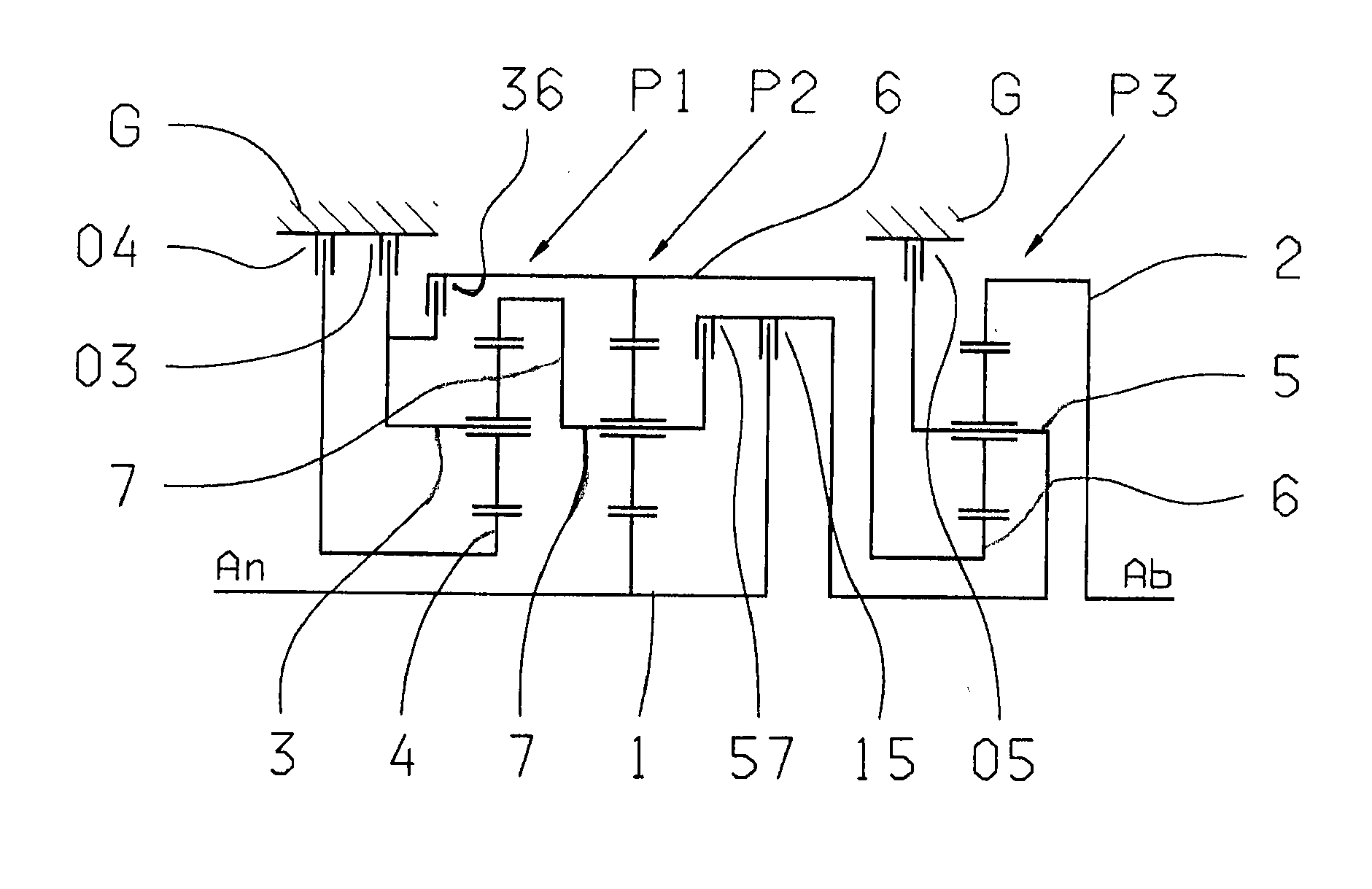
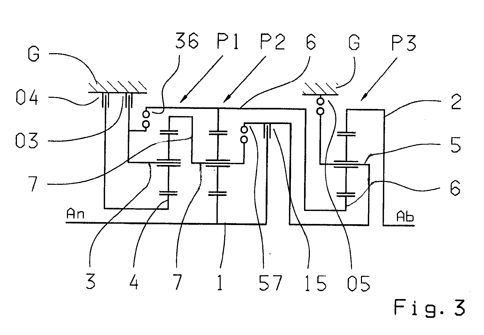
[0037]FIG. 1 shows a multi-step transmission according to the invention, with a drive input shaft 1 (An) and a drive output shaft 2 (Ab), which are arranged in a housing G of the transmission. Three planetary gearsets P1, P2, P3 are provided, which are preferably designed as negative planetary gearsets. In the embodiment shown in FIG. 1 the planetary gearsets are arranged one after another in the axial direction, in the sequence of P1, P2 and P3.

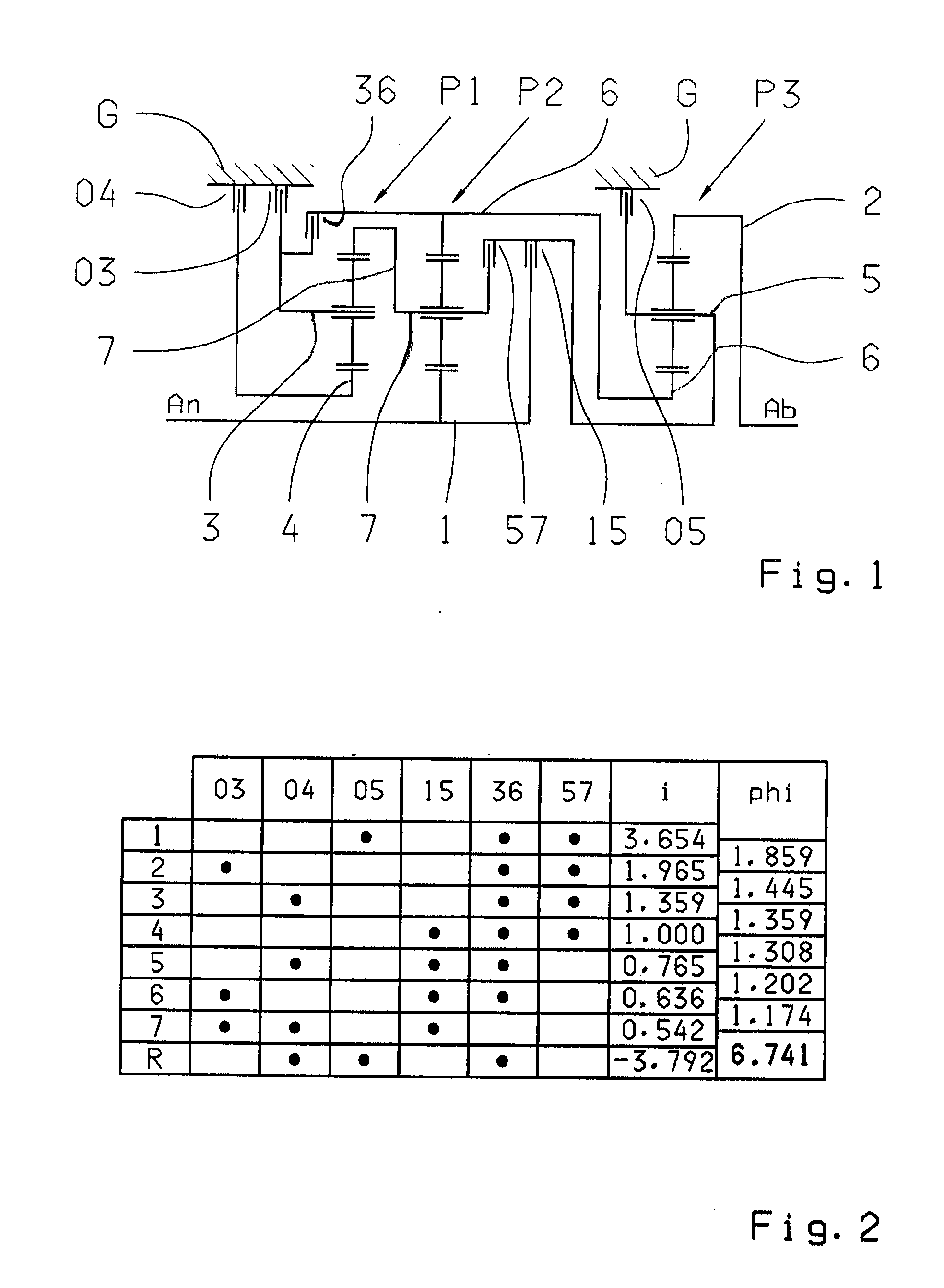
[0038]As can be seen in FIG. 1, six shift elements are provided, namely three brakes 03, 04, 05 and three clutches 15, 36 and 57.

[0039]With these shift elements, seven forward gears and one reversing gear can be engaged by selective shifting. The multi-step transmission according to the invention has a total of seven rotary shafts, namely shafts 1, 2, 3, 4, 5, 6 and 7.

[0040]According to the invention, in the multi-step transmission of FIG. 1 it is provided that the drive input takes place via shaft 1, which is permanently connected to the su...


PUM


Abstract

A multi-step transmission with forward and reverse gears comprises planetary gearsets, shafts and shift elements. The input shaft is coupled to the sun gear of gearset (P2) and, via a clutch (15), to a shaft (5) which is coupled to the carrier of gearset (P3) and, via brake (05), to the transmission housing and, via clutch (57), to shaft (7). Shaft (7) is coupled to the carrier of gearset (P2) and the ring gear of gearset (P1). Shaft (6) is coupled to the sun gear of gearset (P3) and the ring gear of gearset (P2) and, via clutch (36), to shaft (3) which is coupled the carrier of gearset (P1) and, via brake (03), to the housing. Shaft (4) is connected to the sun gear of gearset (P1) and can be coupled, via brake (04), to the housing. The output shaft (2) is connected to the ring gear of gearset (P3).

Description

[0001]This application is a National Stage completion of PCT / EP2008 / 054966 filed Apr. 24, 2008, which claims priority from German patent application serial no. 10 2007 022 776.2 filed May 15, 2007.FIELD OF THE INVENTION[0002]The present invention concerns a multi-step transmission of planetary structure, in particular an automatic transmission for a motor vehicle.BACKGROUND OF THE INVENTION[0003]In the prior art, automatic transmissions, especially ones for motor vehicles, comprise planetary gearsets which are shifted by means of frictional or shift elements such as clutches and brakes, and which are usually connected to a starting element that can be operated in slipping mode and can optionally be provided with a bridging clutch such as a hydrodynamic torque converter or a fluid clutch.[0004]A transmission of this kind is described in EP 0 434 525 A1. It comprises essentially a drive input shaft and a drive output shaft arranged parallel to one another, a double planetary gearset a...

Claims


Application Information

Patent Timeline
Patent Type & Authority Applications(United States)
IPC IPC(8): F16H47/08F16H3/66
CPCF16H3/66F16H2200/0056F16H2200/2064F16H2200/2046F16H2200/201
Inventor GUMPOLTSBERGER, GERHARD
Owner ZF FRIEDRICHSHAFEN AG
Why Eureka
Try Eureka