
Ecology valve fuel return system operable in fluid isolation during gas turbine engine shut-down

a gas turbine engine and fluid return technology, applied in the direction of engine starters, turbine/propulsion engine ignition, machines/engines, etc., can solve the problems of reducing the volume of fuel available for vaporization to the atmosphere and deterring coking of manifold nozzles

Active Publication Date: 2010-06-03
HONEYWELL INT INC
View PDF13 Cites 31 Cited by
  • Summary
  • Abstract
  • Description
  • Claims
  • Application Information

AI Technical Summary

Benefits of technology

The patent describes a fuel return system for a gas turbine engine that includes an ecology valve. The ecology valve is a sliding piston that controls the movement of fuel between a storage position and a return position. The system also includes a fuel routing assembly that can route fuel from the storage chamber to the engine in both start-up and shut-down modes. The technical effect of this system is to improve fuel efficiency and reduce emissions by controlling the movement of fuel and optimizing fuel return during engine operation.

Problems solved by technology

Advantageously, by removing a predetermined volume of burn fuel from the fuel manifolds upon GTE shut-down, such piston / reservoir EV fuel return systems decrease the volume of fuel available for vaporization to the atmosphere and deter coking of the manifold nozzles.
However, by returning this withdrawn burn fuel directly to the fuel manifold when GTE operation is again initiated, such piston / reservoir EV fuel return systems may disrupt the GTE's predetermined flow schedule and thereby comprise ideal engine light-off conditions.

Method used


Image

  • Ecology valve fuel return system operable in fluid isolation during gas turbine engine shut-down
  • Ecology valve fuel return system operable in fluid isolation during gas turbine engine shut-down
  • Ecology valve fuel return system operable in fluid isolation during gas turbine engine shut-down

Examples


Embodiment Construction

[0010]The following Detailed Description is merely exemplary in nature and is not intended to limit the invention or the application and uses of the invention. Furthermore, there is no intention to be bound by any theory presented in the preceding Background or the following Detailed Description.

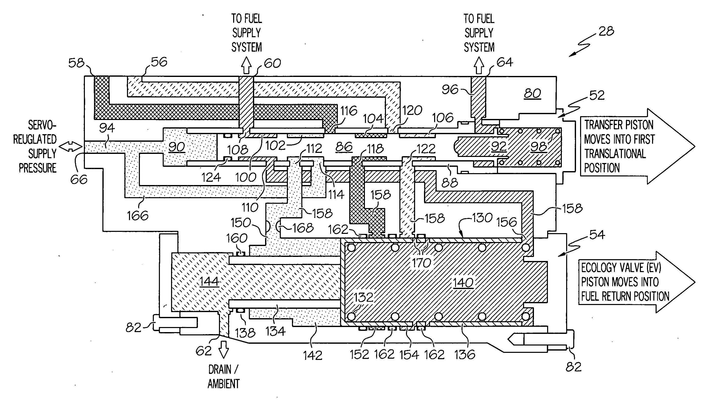
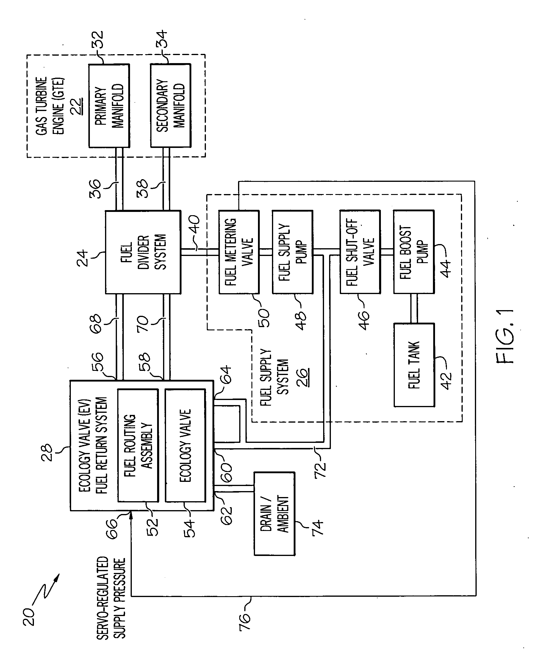
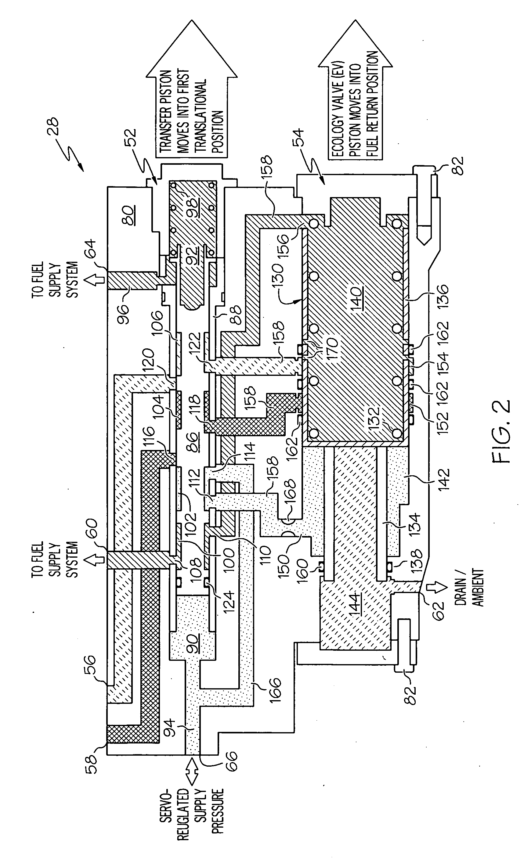
[0011]FIG. 1 is a simplified block diagram of an exemplary fuel control assembly 20 suitable for use in conjunction with a gas turbine engine (GTE) 22 of the type commonly deployed on an aircraft. GTE 22 may be utilized as, for example, a jet engine to provide propulsion to a host aircraft. Alternatively, GTE 22 may be included within an auxiliary power unit (APU) utilized to provide electrical power, pressurized air, and / or hydraulic pressure to various systems aboard the aircraft. For purposes of explanation, fuel control assembly 20 is shown in FIG. 1 as including three main sub-systems: (i) a fuel divider system 24, (ii) a fuel supply system 26, and (iii) an ecology valve (EV) fuel retur...


PUM


Abstract

In one embodiment, an ecology valve (EV) fuel return system includes a housing assembly, an ecology valve, and a fuel routing assembly. The ecology valve includes an EV piston slidably disposed within the housing assembly for movement between a fuel storage position and a fuel return position, a fuel storage chamber defined by the EV piston and the housing assembly, and an EV control chamber defined by the EV piston and the housing assembly. The fuel routing assembly, which is fluidly coupled to the EV control chamber and to the fuel storage chamber, is configured to route fuel: (i) from the fuel storage chamber to a fuel supply system when a gas turbine engine (GTE) is in a start-up mode, and (ii) from the first fuel manifold and from the EV control chamber to the fuel storage chamber when the GTE is in a shut-down mode.

Description

TECHNICAL FIELD[0001]The present invention relates generally to aircraft fuel control systems and, more particularly, to an ecology valve (EV) fuel return system suitable for use in conjunction with a gas turbine engine (GTE) that receives fuel from a fuel tank wherein the EV return system is operable even when fluidly isolated from the fuel tank during GTE shut-down.BACKGROUND[0002]Auxiliary power units (APUs) are commonly deployed on aircraft to provide an efficient source of electrical power, pressurized air, and / or hydraulic pressure. Among other components, an APU may include a gas turbine engine (GTE) having one or more fuel manifolds disposed within a combustion chamber. The fuel supply system includes, amongst other components, a fuel tank, a boost pump, a fuel supply pump, and a fuel metering valve. The manifolds include a series of nozzles (e.g., air blast nozzles and / or atomizer nozzles) that spray the burn fuel into the APU's combustion chamber. The resulting air-fuel mi...

Claims


Application Information

Patent Timeline
Patent Type & Authority Applications(United States)
IPC IPC(8): F02C9/26
CPCF02C7/232F02C7/236F05D2260/85F05D2220/50F02C9/26
Inventor LAWRENCE, DAVIDFUTA, PAULPORTOLESE, LARRY
Owner HONEYWELL INT INC
Learn More