Pressure Equalizing Housing Device

a technology of pressure equalizing housing and housing plate, which is applied in the direction of steam traps, electrical apparatus casings/cabinets/drawers, electrical instruments, etc., can solve the problems of moisture build-up in the housing, heavy impact on the performance of electronic and other instruments, and irreversible damage to the components of the instrument, etc., to reduce the penetration capability of moisture and/or other contaminators into the housing.

Inactive Publication Date: 2010-06-03
KERETH YEFIM
View PDF5 Cites 6 Cited by
  • Summary
  • Abstract
  • Description
  • Claims
  • Application Information

AI Technical Summary

Benefits of technology

[0004]It is therefore a broad object of the present invention to provide a pressure equalizing housing devi

Problems solved by technology

Electro-optical, electronic and other instruments may be heavily affected, and their components may be irreversibly damaged, by excessive moisture.
Housings, enclosing cameras, optics, electronics and instruments, undergo thermal cycling by external or internal heat source(s) and due to on/off cycling within the enclosure, result in moisture built-up therein.
Ambient air, however, may be contaminated by dust and other contaminants, unwanted within the housing enclosur

Method used


Image

  • Pressure Equalizing Housing Device
  • Pressure Equalizing Housing Device
  • Pressure Equalizing Housing Device

Examples


Embodiment Construction

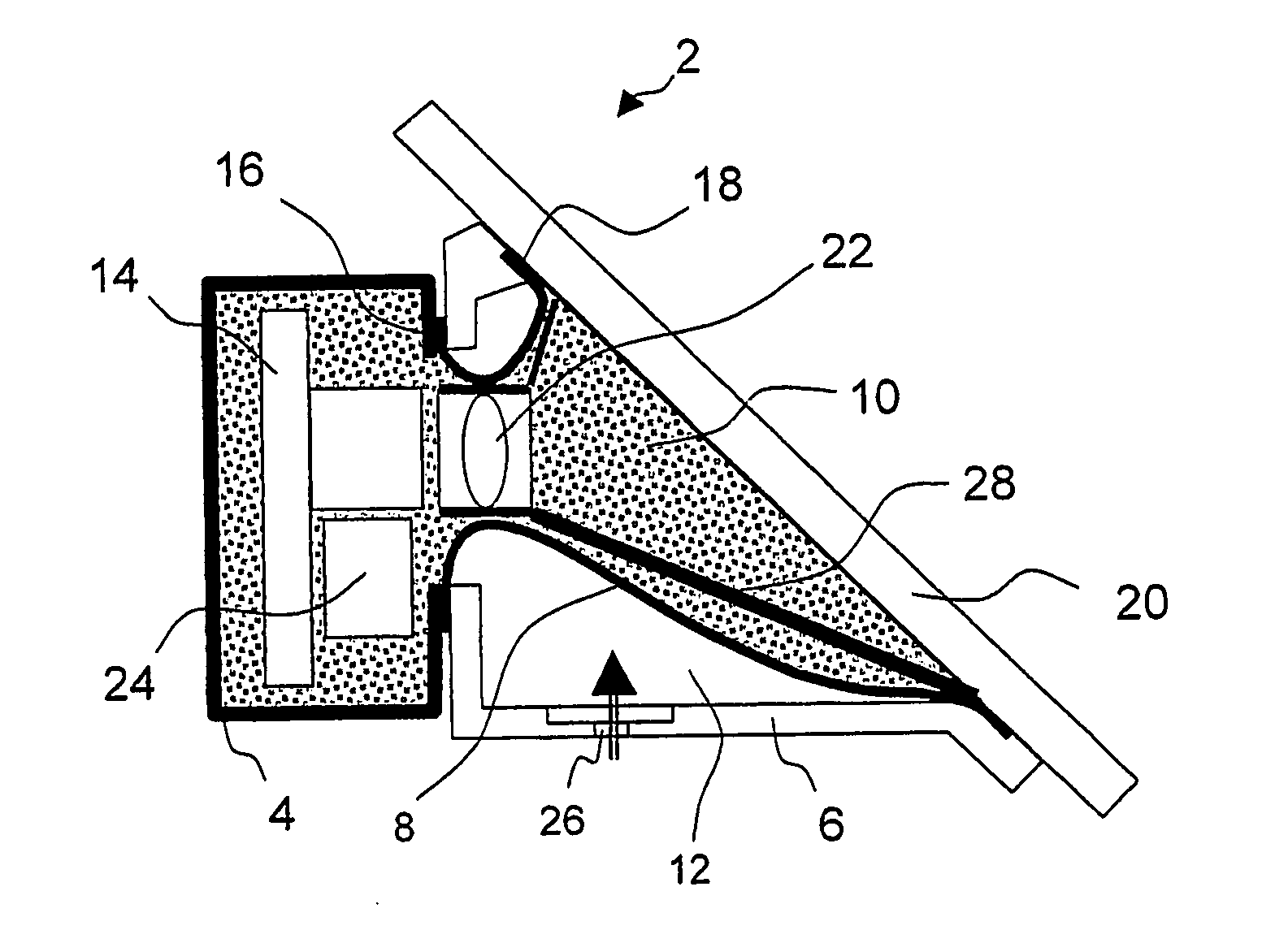
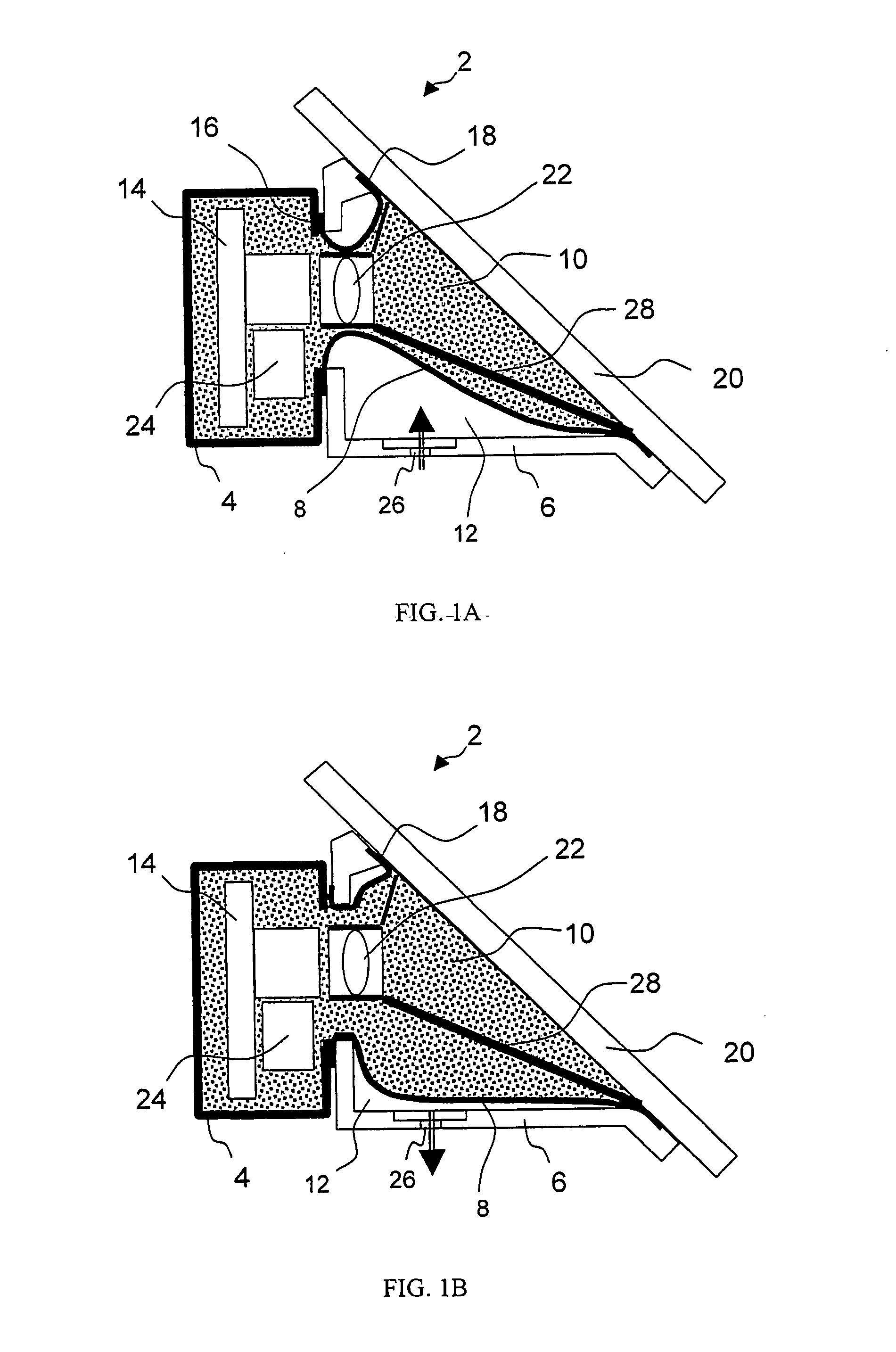
[0012]FIGS. 1A and 1B are schematic side cross-sectional views of the pressure equalizing housing device 2 in two operational states. The device 2 consists of a single, rigid housing 4 advantageously, a two-part housing, a first housing part 4 and a second housing part 6, enclosing a fluid, such as air, nitrogen etc., and an expandable and retractable fluid impermeable member 8, e.g., configured as a sleeve, a bellows, a tube or a vessel, acting as a pressure-equalizer based on volume variation under the pressure gradient or a difference of fluid pressure between the interior 10 (hereinafter also referred to as “functional space”10) of the member 8, and the exterior 12 of the member 8 (hereinafter also referred to as “non-functional space”12). Continuous volume change of the member 8facilitates maintaining of the pressure difference between the captured fluid in the functional space 10 and the non-functional space 12, e.g., ambient air, as low as possible, thereby reducing the risk ...


PUM


Abstract

There is provided a pressure-equalizing housing device, including a rigid housing having a coupling end and configured to contain at least one instrument. The coupling end of the housing is adapted to be sealable to a radiation transmittable surface. An opening made in a wall of the housing enables fluid to pass therethrough, and the housing and surface delimit an interior space communicating with the exterior of the housing via the opening. There is also provided a pressure-influenced member forming an expandable and retractable volume body, a portion of which member is located adjacent to, or the interior of which member communicates with, the opening, for equalizing the pressure inside and outside the housing.

Description

FIELD OF THE INVENTION [0001]The present invention relates to a pressure equalizing housing device for preventing the entrance of moisture or other contaminators into the interior of the housing device.BACKGROUND OF THE INVENTION[0002]Electro-optical, electronic and other instruments may be heavily affected, and their components may be irreversibly damaged, by excessive moisture. As used herein, the term “moisture” is intended to refer to water which is diffused, penetrated or condensed from the ambient atmosphere, whether in liquid or vapor form. Housings, enclosing cameras, optics, electronics and instruments, undergo thermal cycling by external or internal heat source(s) and due to on / off cycling within the enclosure, result in moisture built-up therein. A relatively simple way of dispensing moisture is to provide greater ambient airflow across, or through, the enclosure. Ambient air, however, may be contaminated by dust and other contaminants, unwanted within the housing enclosu...

Claims


Application Information

Patent Timeline
IPC IPC(8): F16T1/00
CPCH05K5/068Y10T137/3003
Inventor KERETH, YEFIM
Owner KERETH YEFIM
Why Eureka
Try Eureka