Wheel suspension assembly and a motor vehicle

a technology for suspension assemblies and motor vehicles, applied in the direction of suspensions, suspension arms, and resilient suspensions, can solve the problems of complex systems of vehicles, overpowering useful control signals, and measurable disturbing noise, etc., to achieve the effect of optimizing human compatible control, improving wheel suspension, and maximizing traction

Inactive Publication Date: 2010-06-03
SWEDISH ADVANCED AUTOMOTIVE BUSINESS
View PDF12 Cites 15 Cited by
  • Summary
  • Abstract
  • Description
  • Claims
  • Application Information

AI Technical Summary

Benefits of technology

[0008]The object of the present invention is to provide an improved wheel suspension for a motor vehicle. More precisely, the object of the present invention is to provide a rear wheel suspension, which aims for maximized traction. Still more precisely, the object of the present invention is to provide a homogeneous contact pressure between the wheel, i.e. the tire, and the road. In addition, it is an object of the present invention to provide a vehicle, which aims for maximized human compatible control for normal as well as for critical unexpected events.

Problems solved by technology

To be noted is the fact that useful control signals and disturbing noise are superimposed and in addition to this, the objectively measurable disturbing noise frequently overpowers the useful control signal.
Vehicles are complex systems with human beings in the control loop.

Method used


Image

  • Wheel suspension assembly and a motor vehicle
  • Wheel suspension assembly and a motor vehicle
  • Wheel suspension assembly and a motor vehicle

Examples


Embodiment Construction

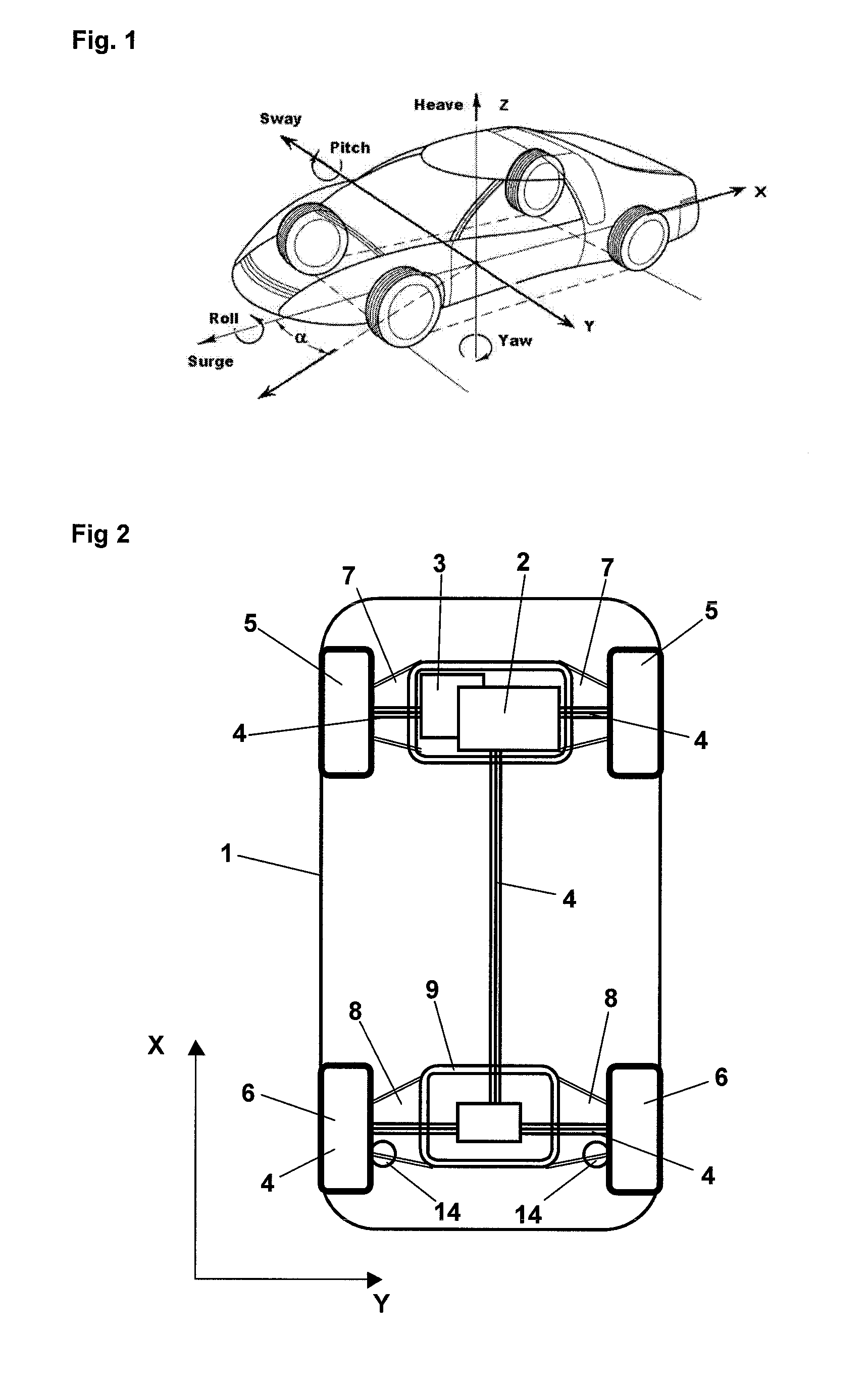
[0042]FIG. 1 discloses the dynamics of a motor vehicle in six degrees of freedom denominated as follows:

Motion up and down=Heave;

Motion left and right=Sway;

Motion fore and aft=Surge;

Angular change around a horizontal lateral direction Y=Pitch;

Angular change around a vertical direction Z=Yaw; and

Angular change around a horizontal longitudinal direction X=Roll.

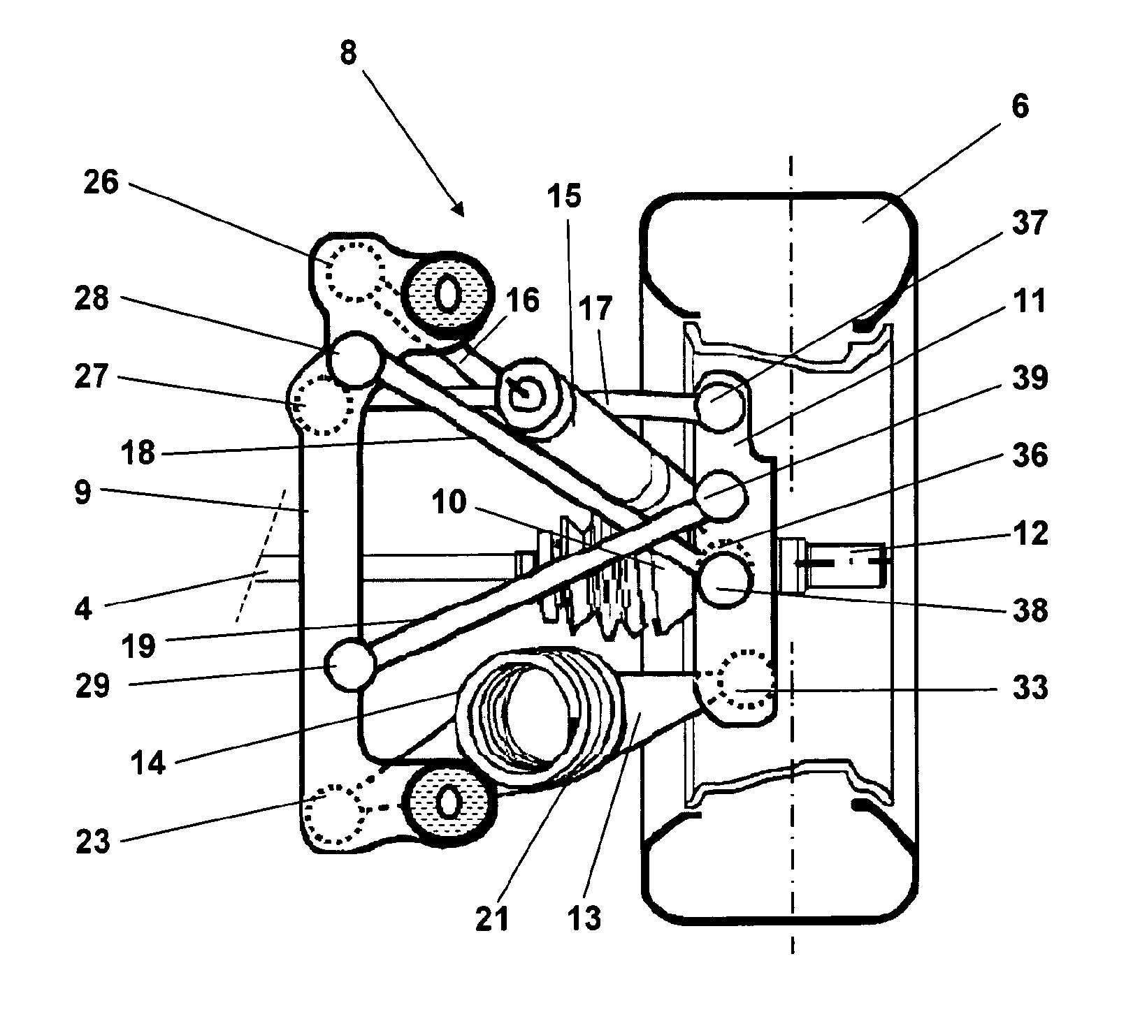
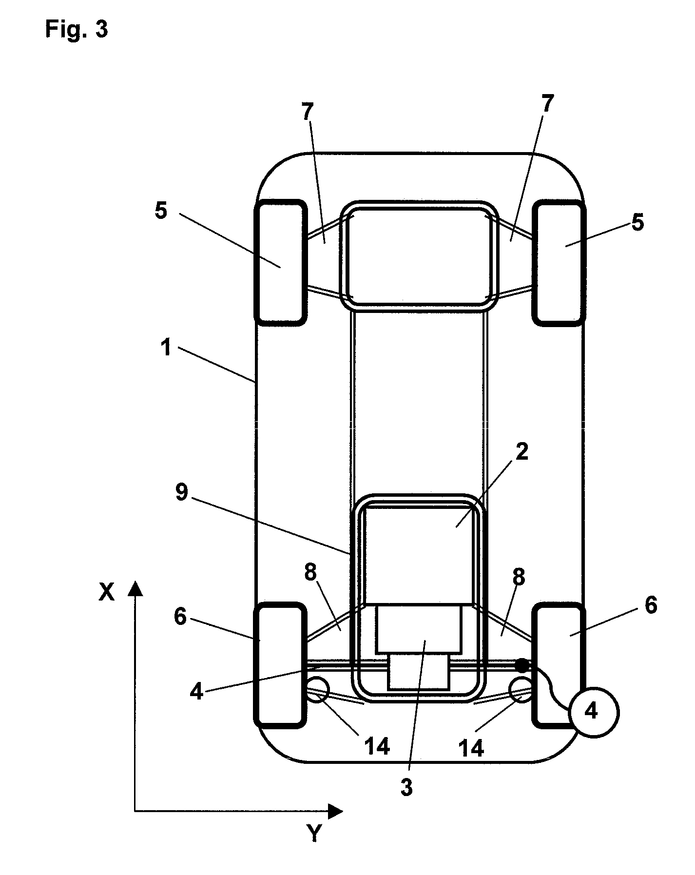
[0043]FIG. 2 discloses a motor vehicle comprising a vehicle body 1 and an engine-transmission assembly, comprising an engine 2 and a transmission 3. The engine 2 is provided at the front of the motor vehicle. The transmission 3 comprises drive shafts 4. The motor vehicle has four tire-wheel assemblies, two front tire-wheel assemblies, each having a front wheel 5, and two rear tire-wheel assemblies, each having a rear wheel 6. The drive shafts 4 connect the transmission 3 to the wheels 5, 6 with different driving configurations such as front-, rear- or all wheel drive of the motor vehicle. The motor vehicle comprises a wheel susp...


PUM


Abstract

A motor vehicle and wheel suspension assembly for a rear wheel of a motor vehicle. The assembly includes a wheel spindle housing supporting a wheel spindle carrying the rear wheel and defining a wheel center. A frame structure is adapted to be connected to a vehicle body or an engine-transmission assembly of the motor vehicle. A spring link extends between the frame structure and the wheel spindle housing and carries a vehicle spring. First and second control links extend between the frame structure and the wheel spindle housing to control the wheel spindle housing to maintain the rear wheel substantially in parallel with a longitudinal direction. A first and second camber link extends between the frame structure and the wheel spindle housing, and intersect each other. An instantaneous center of motion is located at a position far outside the wheel and then rearward the wheel, or far inside the wheel and then forward the wheel.

Description

FIELD OF THE INVENTION[0001]The present invention refers generally to the suspension of a rear wheel of a motor vehicle, especially passenger cars, sport utilities (SUVs) and light trucks. More specifically, the present invention refers to a wheel suspension assembly as defined in the pre-characterizing portion of claim 1. The present invention also refers to a motor vehicle having a wheel suspension assembly as defined in the pre-characterizing portion of claims 22 and 23.BACKGROUND OF THE INVENTION AND RELATED ART[0002]The wheel suspension assembly for a motor vehicle connects the architecture of the sprung vehicle mass to the architecture of the non-sprung and rotating tire-wheel assembly. Furthermore, the wheel suspension assembly controls the motion pattern of the tire-wheel assembly with respect to the external impact from the road as well as to the internal impact from the propelling, braking and steering as initiated by the driver through the engine-transmission assembly, th...

Claims


Application Information

Patent Timeline
Patent Type & Authority Applications(United States)
IPC IPC(8): B60G11/16B60K17/00
CPCB60G3/26B60G7/008B60G2200/18B60G2200/46B60G2200/184B60G2204/1244B60G2204/148B60G2204/4106B60G2200/462B60G2204/14
Inventor ROLAND, MAGNUSBURENIUS, GUNNAR
Owner SWEDISH ADVANCED AUTOMOTIVE BUSINESS
Why Eureka
Try Eureka