Radar device

Active Publication Date: 2010-06-03
MITSUBISHI ELECTRIC CORP
View PDF2 Cites 14 Cited by
  • Summary
  • Abstract
  • Description
  • Claims
  • Application Information

AI Technical Summary

Benefits of technology

[0017]In the radar device according to the present invention, there is added no correlation matrix generated from the peak frequency spectrum having the peak frequency within the given frequency range, in which noises generated by a transceiver or an A/D converter, an offset voltage caused by the variation or the temperature characteristics, a reflection signal from a stopping target, or the like is superimposed on the receive

Problems solved by technology

However, in the case where at least one of the up-period peak frequency and the down-period peak frequency falls within a given frequency range, when the correlation matrix generated from the peak frequency spectrum having a peak frequency within the given frequency range is added to the correlation matrix generated from the peak frequency spectrum having a peak frequency outside of the given frequency range, there arises such a problem that the direction of the target cannot be accurately calculated, or the number of targets is miscalculated.
However, after the combination has been completed, in the case where any one of an up-period peak frequency fbu_a and a down-period peak frequency fbd

Method used


Image

  • Radar device
  • Radar device
  • Radar device

Examples


first embodiment

[0029]A radar device according to a first embodiment of the present invention is described with reference to FIGS. 1 to 5. FIG. 1 is a diagram illustrating a configuration of the radar device according to the first embodiment of the present invention. In the following description, the same symbols indicate identical or corresponding parts in the respective drawings.

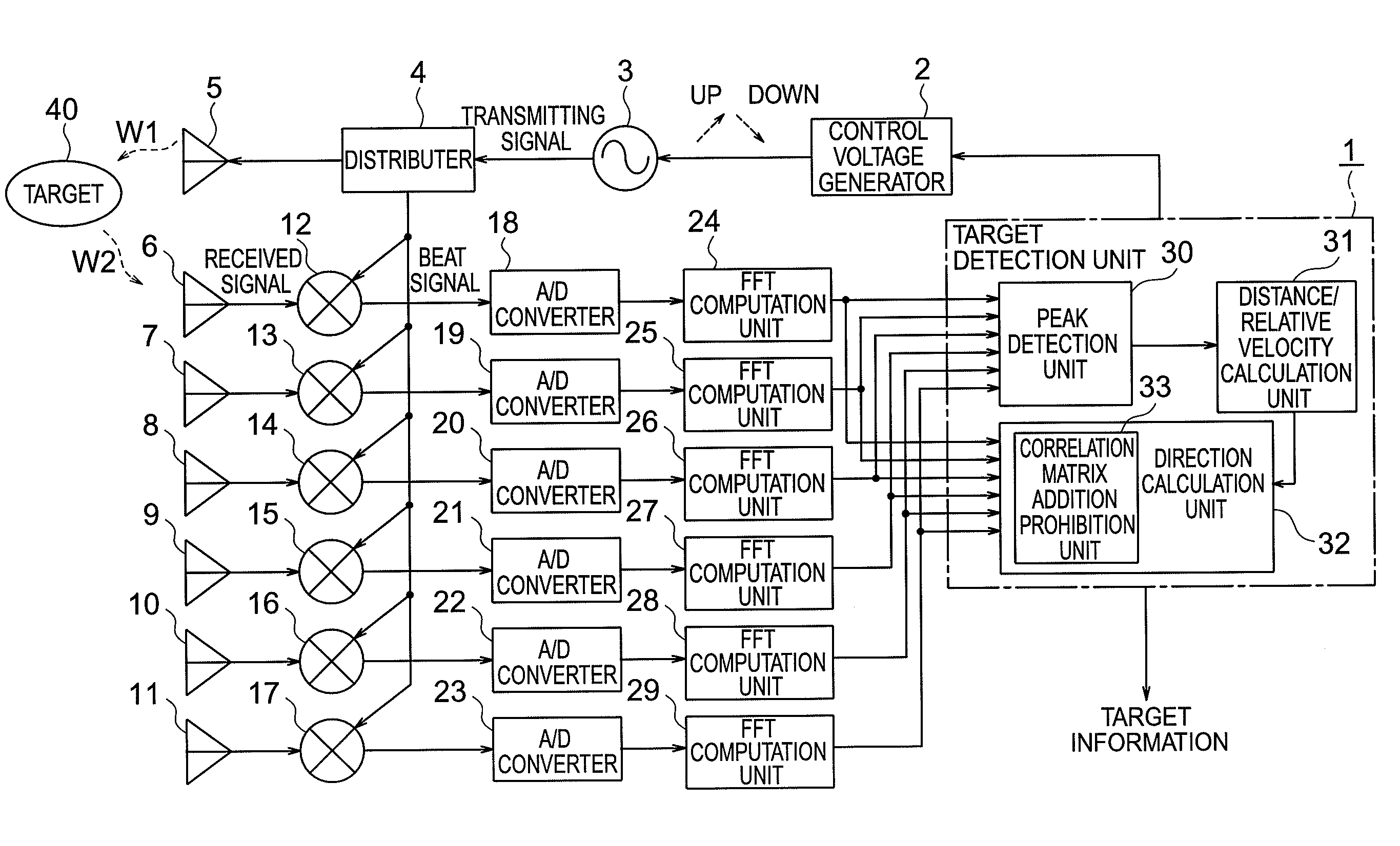
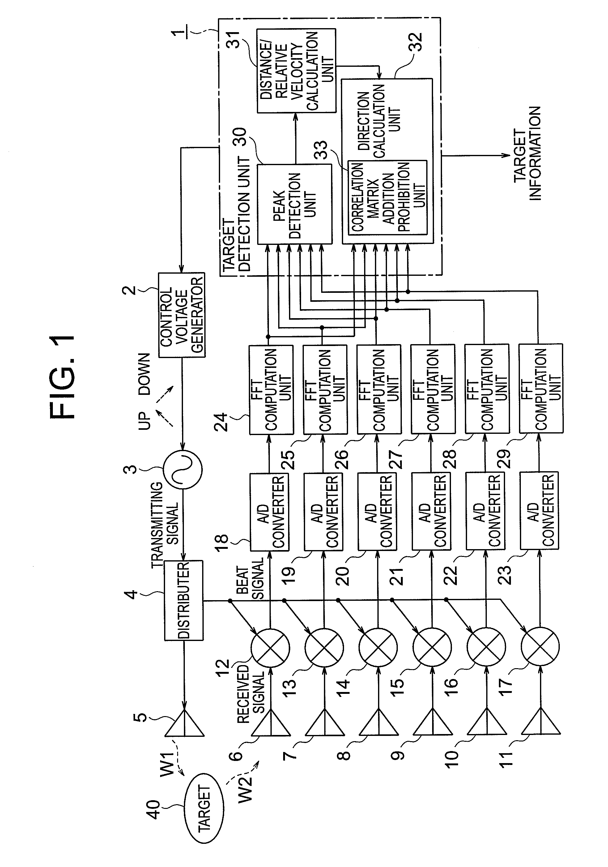
[0030]Referring to FIG. 1, the radar device according to the first embodiment of the present invention includes: a target detection unit 1 made up of a microcomputer; a control voltage generator 2 that outputs a control voltage under control of the target detection unit 1; a voltage controlled oscillator (VCO) 3 that outputs a transmitting signal having a frequency modulated in up / down on the basis of the control voltage; a distributer 4 that distributes a transmitting signal; and a transmitting antenna 5 (transmitting means) that emits a transmitting signal W1 to a target 40.

[0031]Referring to FIG. 1, the radar device al...

second embodiment

[0070]A radar device according to a second embodiment of the present invention is described with reference to FIGS. 6 and 7A to 7C. The configuration of the radar device according to the second embodiment of the present invention is identical with that of the first embodiment.

[0071]In the first embodiment, addition of the correlation matrix is prohibited when the peak frequencies fbu and fbd are in the vicinity of 0. On the other hand, in the second embodiment, addition of the correlation matrix is prohibited when the peak frequencies fbu and fbd fall within the frequency range in which a stopping target exists.

[0072]Next, the operation of the radar device according to the second embodiment of the present invention is described with reference to the accompanying drawings. FIG. 6 is a flowchart illustrating the operation of a target detection unit of the radar device according to the second embodiment of the present invention. FIGS. 7A to 7C are diagrams illustrating the amplitude of...

third embodiment

[0084]A radar device according to a third embodiment of the present invention is described with reference to FIGS. 8 to 10. FIG. 8 is a diagram illustrating the configuration of a radar device according to the third embodiment of the present invention.

[0085]In the third embodiment, with the configuration illustrated in FIG. 8, when a difference between an up-period peak frequency fbu_a of a target a (a=1, . . . , K−1: K≧2) and an up-period peak frequency fbu_b of a target b (b=a+1, . . . , K: K≧2) falls within a given frequency range, the direction calculation unit 32 stores the overlapping peak frequency fbu_a of the target a and the overlapping peak frequency fbu_b of the target b in an overlapping peak frequency storage unit 34.

[0086]Alternatively, when a difference between a down-period peak frequency fbd_a of the target a (a=1, . . . , K−1) and a down-period peak frequency fbd_b of the target b (b=a+1, . . . , K) falls within a given frequency range, the direction calculation u...


PUM


Abstract

Provided is a radar device capable of accurately calculating directions and the number of targets. A direction calculation unit includes a correlation matrix addition prohibition unit that prohibits, when a peak frequency in a plurality of modulation periods of a target is in the vicinity of 0, addition of a correlation matrix generated from a peak frequency spectrum having the peak frequency in the vicinity of 0, and calculates the direction of the target on the basis of a summed correlation matrix in which correlation matrices generated from peak frequency spectra having peak frequencies out of the vicinity of 0.

Description

BACKGROUND OF THE INVENTION[0001]1. Field of the Invention[0002]The present invention relates to a radar device that calculates target information on the basis of a reflected signal when a transmitting signal (electric wave) is emitted to a target object (hereinafter, referred to as “target”), and the reflected signal based on the transmitting signal from the target is received by a plurality of receiving antennas.[0003]2. Description of the Related Art[0004]Up to now, as a radar device for calculating a distance to a target or a relative velocity thereto, there has been known a frequency modulated radar device that transmits a transmitting signal having a successively modulated frequency to the target, and receives a reflected signal from the target to calculate a distance to the target and a relative velocity thereto.[0005]As a method of calculating a target direction in the radar device of this type, there has been known a method of calculating a direction of the target by mechan...

Claims


Application Information

Patent Timeline
IPC IPC(8): G01S13/00
CPCG01S3/74G01S13/931G01S13/584G01S13/345
Inventor NAKAGAWA, KADO
Owner MITSUBISHI ELECTRIC CORP
Why Eureka
Try Eureka