Multi-Band Antenna

a multi-band antenna and antenna technology, applied in the direction of antennas, antenna details, elongated active element feed, etc., can solve the problems of reducing the size of the antenna, unable to cover multiple frequencies at the same time, and conventional antennas cannot cover multiple frequencies, so as to achieve the effect of reducing the size of the multi-band antenna and occupying a smaller spa

Inactive Publication Date: 2010-06-03
CHENG UEI PRECISION IND CO LTD
View PDF5 Cites 34 Cited by
  • Summary
  • Abstract
  • Description
  • Claims
  • Application Information

AI Technical Summary

Benefits of technology

[0008]As described above, the arrangement of the first radiating element, the second radiating element and the third radiating element makes the multi-band antenna transmit and receive multiple bands. The first radiating element spatially fences the second edge and the fourth edge of the base plate, the second radiating element and the third radiating element tortuously extend from the third edge of the base plate, which reduces the size of the multi-band antenna and makes the multi-band antenna take up smaller space when assembled in a portable wireless communication device.

Problems solved by technology

However, each of these antennas could not overall meet the demand of operating at multiple frequencies while the sizes thereof are reduced.
Therefore, a disadvantage is exposed that the conventional antennas cannot cover multiple frequencies but occupy desirable smaller space concurrently.

Method used


Image

  • Multi-Band Antenna
  • Multi-Band Antenna

Examples


Embodiment Construction

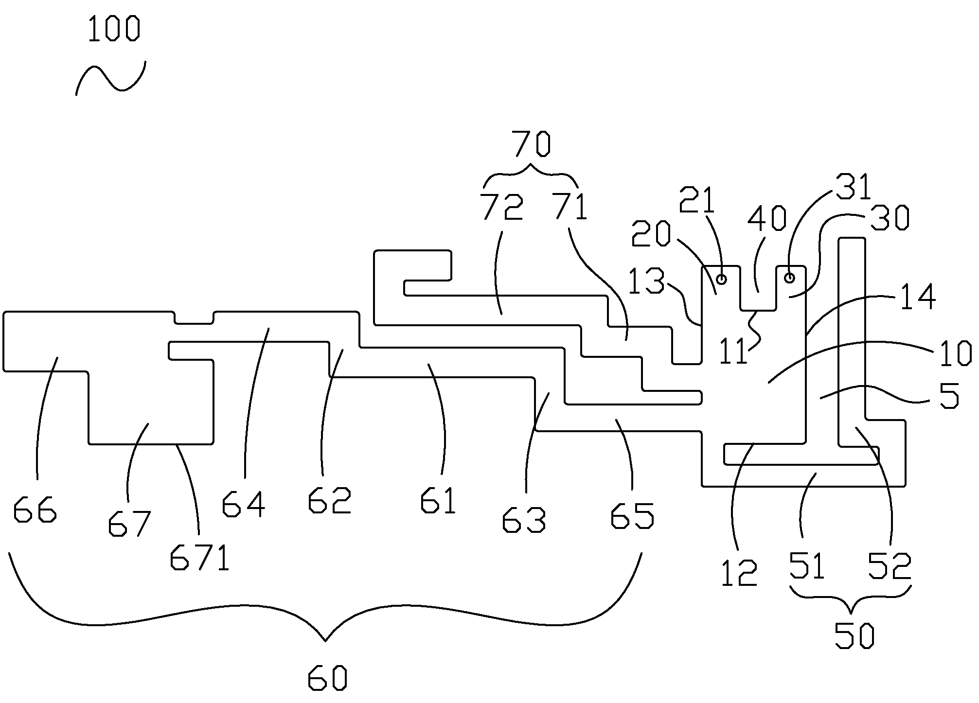
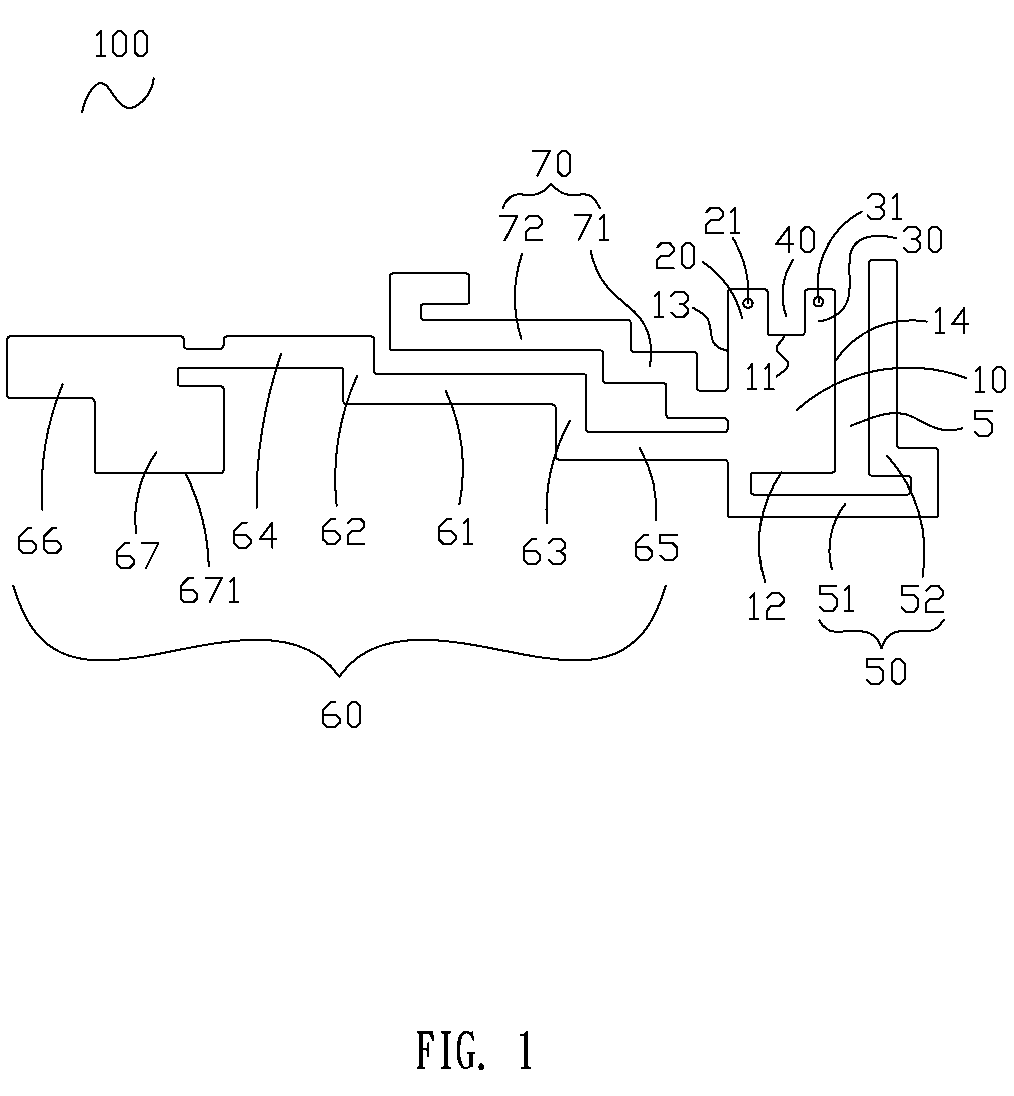
[0011]With reference to FIG. 1, a multi-band antenna 100 according to the invention is shown. The multi-band antenna 100 includes a substantially rectangular base plate 10 which defines a first edge 11, a second edge 12 opposite to the first edge 11, a third edge 13 and a fourth edge 14 both connecting the first edge 11 and second edge 12 and opposite to each other.

[0012]A feeding portion 20 is extended from the first edge 11 and adjacent to the third edge 13. The feeding portion 20 defines a feeding point 21 thereon. A ground portion 30 is extended from the first edge 11 and adjacent to the fourth edge 14. The ground portion 30 defines a ground point 31 thereon. And an opening 40 is defined between the feeding portion 20 and the ground portion 30 to form a simulation inductance therebetween for tuning bandwidth and input impedance of the multi-band antenna 100 to realize impedance matching between the multi-band antenna 100 and a feeding cable (not shown).

[0013]A first radiating el...


PUM


Abstract

A multi-band antenna includes a base plate, a first radiating element, a second radiating element and a third radiating element. The base plate has a first edge, a second edge opposite to the first edge, a third edge and a fourth edge both connecting the first and second edges and opposite to each other. A feeding portion and a ground portion are both extended from the first edge and respectively adjacent to the third edge and the fourth edge, and an opening is formed between the feeding portion and the ground portion. The first radiating element extends from a portion of the second edge adjacent to the third edge and spatially fences the second edge and the fourth edge. The second and third radiating elements tortuously extend from the third edge and are arranged adjacent to each other.

Description

BACKGROUND OF THE INVENTION[0001]1. Field of the Invention[0002]The present invention relates to a multi-band antenna, and more particularly to a multi-band antenna having reduced size.[0003]2. The Related Art[0004]In recent years, portable wireless communication devices are becoming progressively popular. In order to communicate with other communication devices, various antennas are assembled in these devices for transmitting and receiving electromagnetic waves. Considering the miniaturization trend of the portable wireless communication device, the size of the antenna should be correspondingly reduced in order to be assembled in the limited space of the portable wireless communication device.[0005]Among present wireless technologies, wireless communication bands include global system for mobile communications (GSM) band about 850 MHz, extended global system for mobile communications (EGSM) band about 900 MHz, digital cellular system (DCS) band about 1800 MHz, personal conferencing...

Claims


Application Information

Patent Timeline
Patent Type & Authority Applications(United States)
IPC IPC(8): H01Q1/38
CPCH01Q1/38H01Q5/371H01Q9/42
Inventor SU, JIA-HUNGTSAI, YUNG-CHIHSHIH, KAIWU, YU-YUAN
Owner CHENG UEI PRECISION IND CO LTD
Why Eureka
Try Eureka